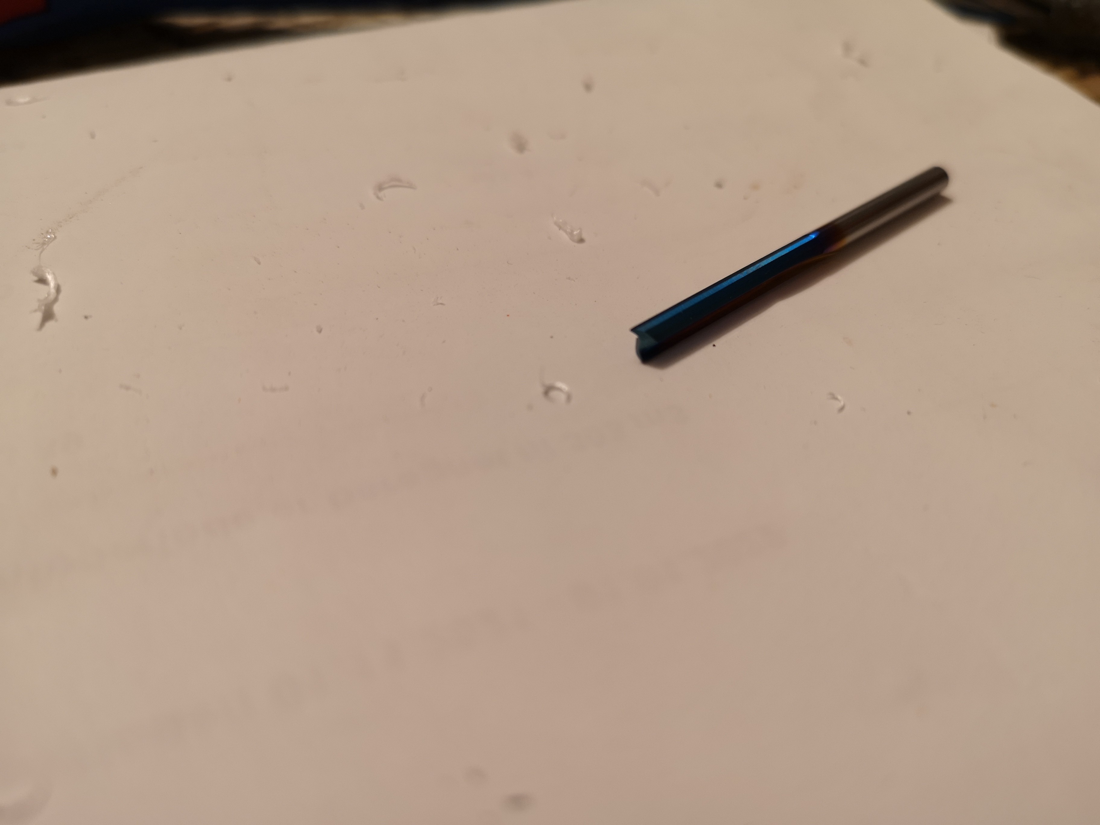
That’s the flute used, i have plenty of these, so wanted to start with breaking these of anything went wrong… I have the Makita RT0700C and set it to max, z was 2mm and speed 3mm/s…
So is this classic missing steps? Pocketing holes goes ok but long cuts fucks up?
What seems strange is the deeper cut, which is 6 mm instead of 2mm looks nicer…
I am thinking about trying to do the same in polystyrene just to clarify its not a firmware issue, the CNC can’t be stopped with the stop button on the display went started, but usually done the little test i started with perfect, and complained about unknown commands M03 and M05 which I had in my gcode…
M3 and M5 turn the spindle (clockwise) on and off, respectively, so if you don’t have a relay or some other sort of spindle control they won’t do anything. For the record, M4 is reverse (counter-clockwise) spindle rotation.
Melting indicates more friction than is good - the chips should “carry away” the heat. I can’t tell from the photo whether that’s a one or two flute tool. Two flutes will mean having to move the tool faster to keep making chips.
Can you blow air at the tool to try and keep things cooler?
I have little practical knowledge of cutting acrylic, but I was just researching this subject for a project I’m designing. Based on what I’ve read, your RPMs are too high, your DOC is too high, your feedrate is too slow, and your cutting would benefit from an endmill made for cutting acrylic.
Try:
17,000 RPM (around 3.0 on the Makita dial)
0.8 t to 1.2 DOC
Feedrate of 11 to 14mm/s
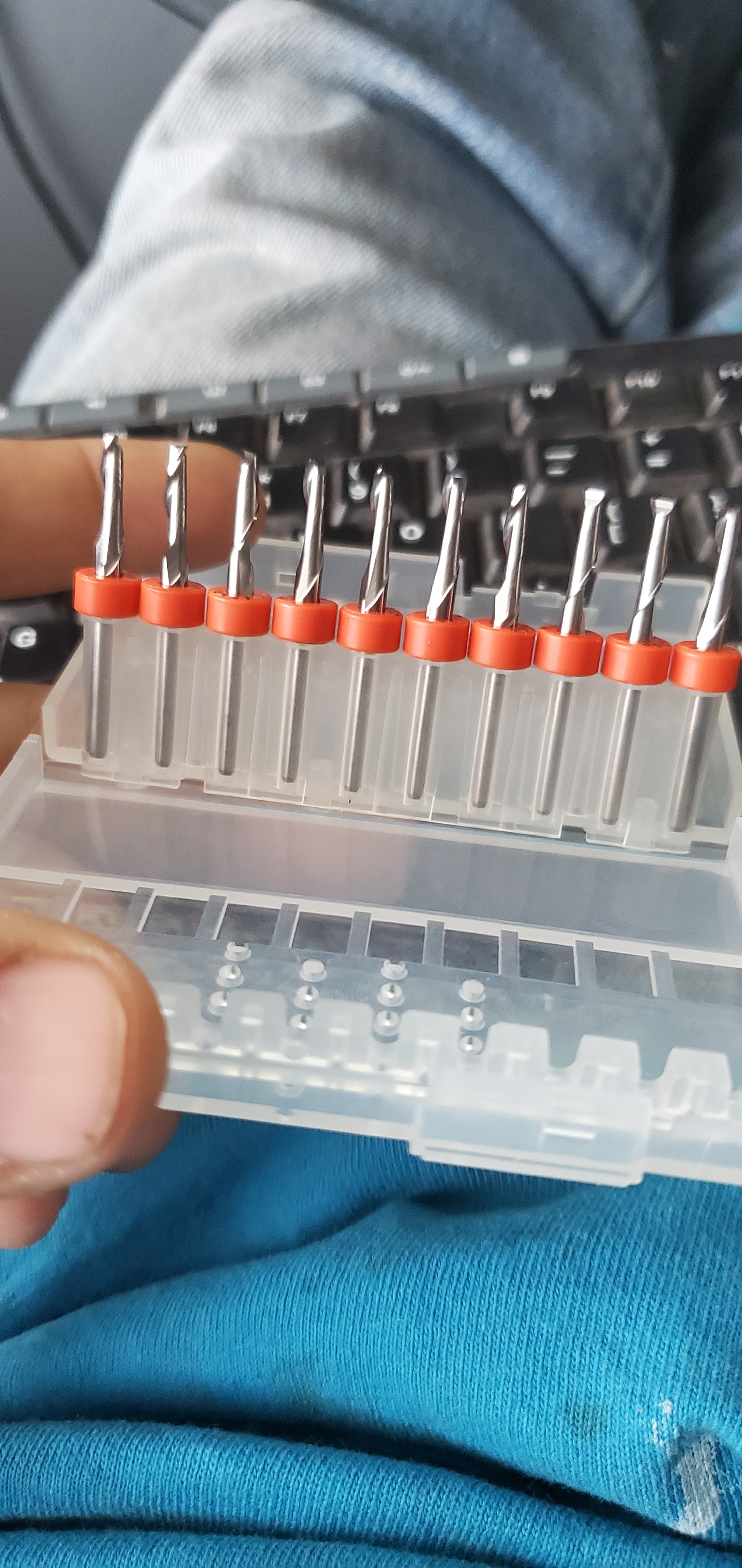
The router bits that do well for acrylic are often referred to as ‘O’ flute endmills, and for our routers, it has been suggested that single flute is better. Info on ‘O’ flute.
Thanks, I should have clarified i knew what M3 and M5 are surposed to do, I just hoped that when I am using my laser, it would turn on/off during travel movement… That’s another problem coming up…
It is a 2 flute bit, I found a 1 flute up cut and gave that a quick test, it was much better.
What was confusing with the first cut was that I had decent I think I had decent chip size, but they did not escape the cut, that goes kind of ok with small pocketing, they stay melted and soft, with the long cut they fuse to the track…
I think you are right about air, but think I need it on all the time, that might blow the chips away…
Lesson learned don’t cut challenging materials with the wrong flute😉 but it seemed so close🤷
One of the benefits of “Laser Mode” is that the laser is automatically disabled during travel moves, and no vertical motion is needed. I don’t know whether laser mode can be enabled/disabled in Marlin without reflashing the firmware. In grbl its a simple $32=1 to enable laser mode and $32=0 to switch back to spindle mode.
I cut a boat load of acrylic, and that’s pretty close to what i used on my 2x4 primo. I cut closer to 2mm DOC, though (0.07"), limited by rigidity. My 1x2 primo cuts 1/8 DOC. Depending on your build, if you have to go shallower, you can probably go much faster. The idea is to make the biggest chip you can make without goofing up your surface or skipping steps. I don’t use air and have no melting.
100% of the time i use the single flute kyocera endmills Ryan sells as the short single flutes (i buy them 10 at a time from drillman1 on ebay).
For Marlin, laser mode must be enabled in the firmware before compiling. V1/Ryan/Jeff enabled laser mode in the firmware they maintain for the Rambo and the SKR boards (the ones they sell and therefore could test). The other firmware versions they maintain would require changing some #defines and recompiling. Laser mode was enabled around version 510 of the firmware.
I think it is enabled, it is not purely my cooking, it is Expertnoobs SKR1.4 TMC 2209 that should be laser plug and play, I had issues with getting to control my neje laser from the TFT panel, probably fucked it up when I changed the Fan_Pin to the neo pixel pin, but now I can control the laser power from the TFT… Next step is to figure out which program to use for laser, many recommend Lightburn, so I think I will try that first…
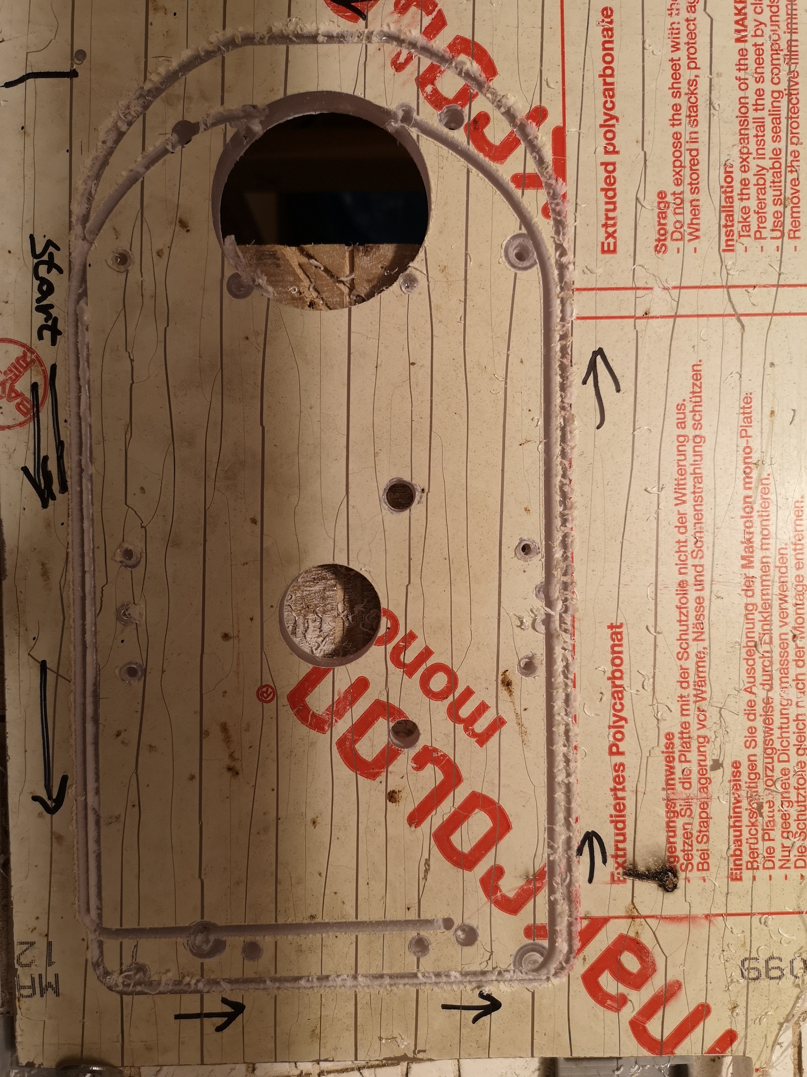
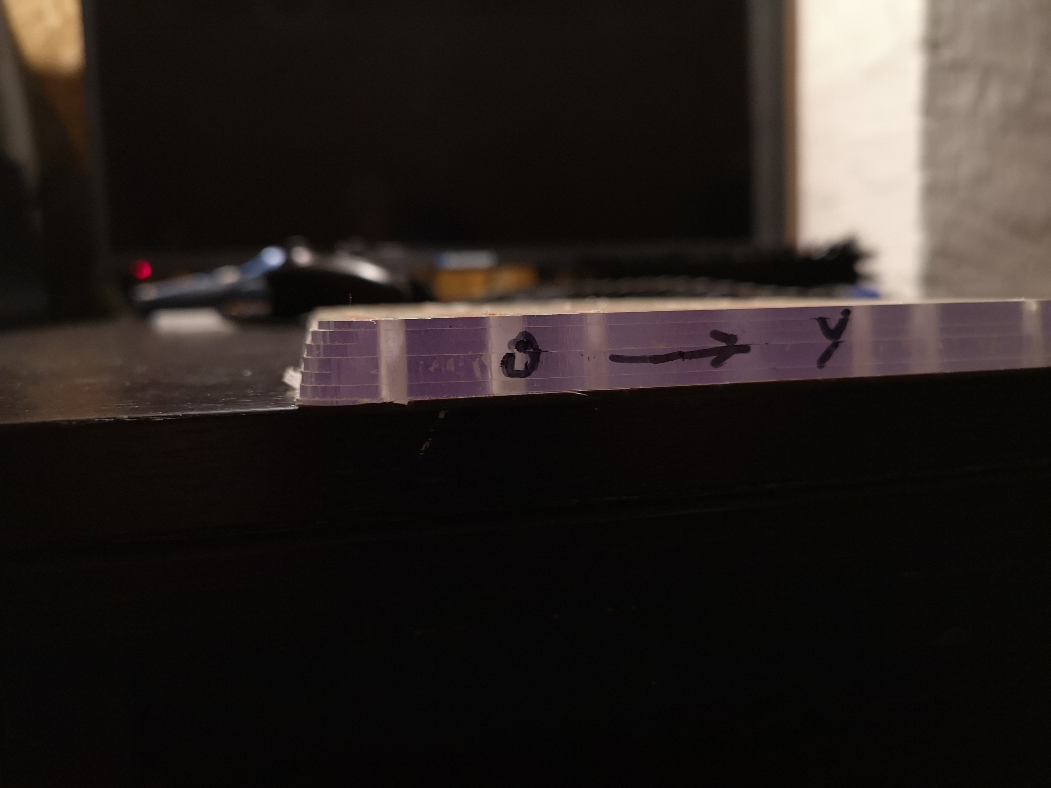
Almost perfect, one of the y axe skipped a bit but don’t think that was my problem…
Pockets came out perfect smooth…
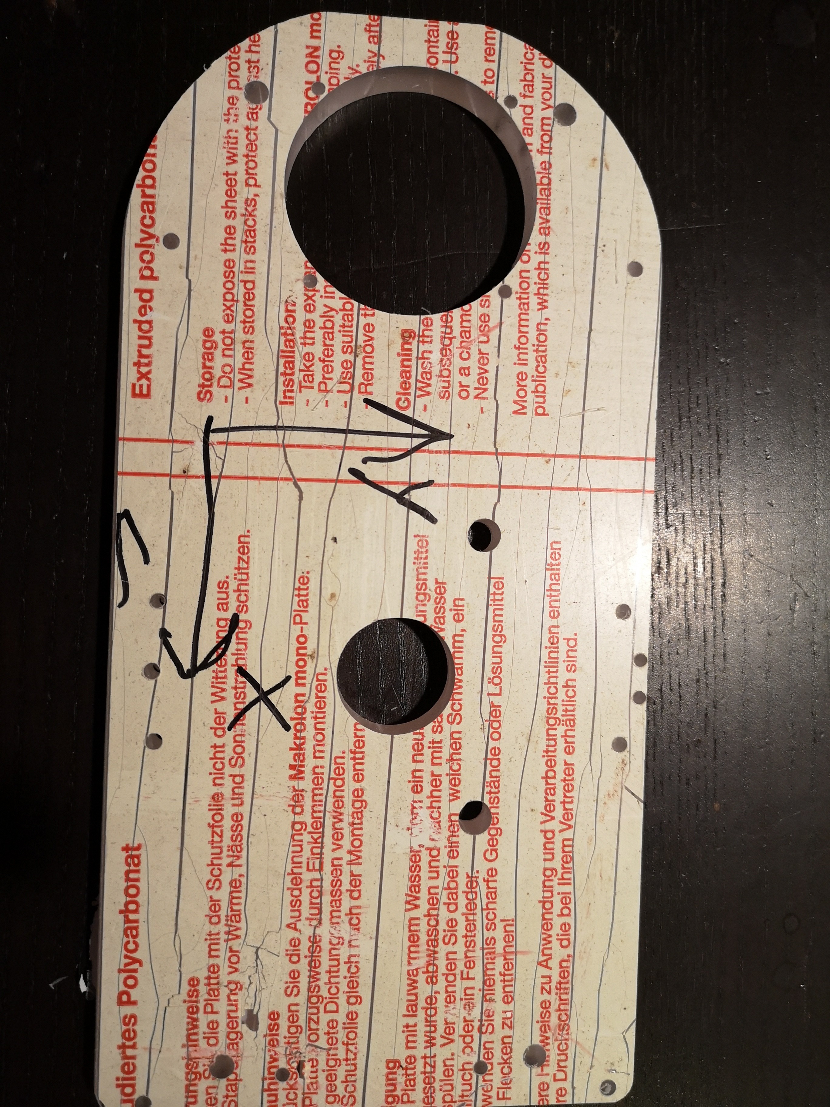
The part cut is strange, the top X cut is perfect (y140), the bottom is steped in 2mm increments in Z direction and 1mm in y direction, starting from the top the part is 5mm to narrow ending in the bottom on the actual measure…
If it’s missed steps, keep in mind that one side will always appear to get smaller towards the top, and the other side, it will just keep cutting deeper. It cannot step inwards as it goes down, so you do not get the same visual effect as you would 3D printing. The opposite side will appear to be perfect, but will in actuality have been cutting away more and more material from above the current cut as it goes down.
So while it will LOOK ok on the other side, it will actually have been cut too small, because the material will have been cut away from the top layers.
That looks like the wheels are slipping to one side. I had a similar problem. I added some 3/4" strips inside the wheels to force them to track straight.
My build does this too and always wondered what was going on. Never thought about the wheels slipping. I just added a trench on my table for the wheels to ride in. Waiting on new belts to test it but seems super solid now.
I kind of noticed that earlier and thought about an extra set of wheels to lock it totally…
Think it is time to act on that and alsomake a better way of tensioning the belts, I am breaking my strips, so belts are tensioned to the max, with strips… And 2800mm of y axis probably is pushing it😉
Yeah i think it would be best with a spring loaded solution, but would be easy just to drill in a M8 bolt with washers and a bearing as wheel on the existing parts… My Y axisv runs on alumina L profiles so quite smooth, but also slippery.,