So…before quitting further development of my mpcnc (cool design, awesome learning experience, lots of fun but with inherent limits that keep me from doing what i want to do sucessfully…no bad feelings at all) and building something else I wanna give it a shot in rethinking/upgrading the center…thingy (first). This is where all the problems come from that i just cannot fix in any other way than reprinting 8hr+ parts over and over without knowing if it will actually help anything or if the design is just not able to handle what i throw at it (i might have hit the limit, nothing against the design). The feeling is absolutely frustrating and i won’t go down that road.
This project will be considered an upgrade to improve existing machines and i dont have any intention to alter the original design with this. More like an optional retrofit for ppl that have hit thier limits and want to push it a little further.
Main Goals are:
More rigidity.
Better adjustment of all individual axis in each individual axis.
Ability to mount diffentent z axis “modules” (including a rework of the stock one)
Before starting I want to ask @vicious1 for explicit consent. Just feels like the right thing to do.
Before coming up with more than an abstract image in my head i also wanna ask for access to the plans, measurements and some models for the mpcnc and the lowider to get the design done as accurately as possible.
The plans and models will be usesd only for the realization of this project and not be made available to any 3rd parties.
No public releases will be made without explicit consent (again…right thing to, respect 'n stuff…)
So here’s the plan:
Use of a reinforced 3-5mm steel angle to keep X/Y aligned as close to 90° as possible.
Mount roller plates to that angle using some sort of interfacing plates (acrylic, hard wood).
2.1 Roller plates can be adjusted with setscrews or shimmed to the correct angle
–> Now we should have a rigid 90° angle riding on X and y paralell to the work surface.
By using 45° angles a Z-Plate will be mounted perpendicular to the 90° XY angle.
Z-Axis will inserted into gudies that mount to the Z-plate. To achive this, the existing Z-Mounts have to be redesigned accordingly.
Profit.
No not really. This thing will get heavy so pipes will most likely become a limiting factor. To add rigidity at this point i plan to insert a square tube into the pipe to increase thier strength.
Even more Weigth added. Nema 17s might hit thier limit. Consider 23s.
This will most likely turn into the biggest sink of time and money i can imagine so…lets’go!
What problem are you trying to fix? As I see it, the limiting factor in the MPCNC is that the gantry tubes bend, and that bend is magnified by the length of the Z axis. Stiffening the centre assembly is unlikely to change that.
Rigidity and adjustability of the center assembly. It’s all in the title. I don’t see that as a general problem, its just a design limitation that i try to push beyond what is possible now because that limitation is getting problematic for me. It’s not that my machine does not work, its just not good enough for what i want.
I could throw it all away and say “F* it” or try to come up with something that others can make use of.
Frame and Gantry tubes can be swapped for solid rails, filled with concrete or otherwise reinforced. Not a big deal.
Motion system can be changed to Nema 23s. Not a big deal.
Center assembly has flex in (its plastic after all) and adjusting the angles is guesswork. Z-Axis cant be changed. Big Deal for me.
I’m no engineer, but it seems to me if it’s extra height in the Z axis that you want without a total redesign, why not consider a counterweight to whatever tool is attached to the central assembly? Wouldn’t that then ensure the force of the mass of the Z axis assembly is always directly down? Depleted uranium would fit the bill perfectly. It’d hardly be noticeable!
A more powerful Z motor may be needed of course, or a finer threaded rod.
I’m a chemist, so if this is nonsense, I apologise.
Please feel free to rework it in any way that makes sense to you! Using words like this are hard to describe the intricacies of what is happening in our heads. All I ask is you license your design the same as mine if it is close to my current work, you will have the same rights as I do with mine and vise versa.
Seems you might need a few dims along the way, I have no issues helping with those but please be patient, I have a 6-7 day backlog of emails and posts right now.
I have a new design I have been working on for a while and I have been tweaking minor things and even with a 0.5mm nozzle one of the parts takes 14-17 hours to print. R&D is not cheap! imagine tweaking something 0.1 degree and waiting that long to see if it is enough or too much.
I built mine with 27mm Gal pipe. It’s pretty rigid. had to do some adjustment. Some sections of 27mm pipe were 27.2 so that added some interest. Pipes were a little lumpy but been sanded and then wore in. It has a 530mm work area and so far is pretty solid.
Did a few test cuts then left briefly while the spindle drove into the work piece and tried to set it on fire.
Project on hold with Primo on the horizon.
And I got some pretty fresh Bosch Rexroth Linear rails off Ebay for dirt cheap, that i will use on a larger (600mm+ in XY dimension) machine in the future.
MPCNC will shrink and be used as a machine to make parts for other machines.
Some thoughts considering pipes and rigidity:
Wall thickness is not to be underestimated (my Stainless pipes come with 1.5mm walls and are wobbly AF, 2mm is much better, although it sounds insignificant).
Mineral Casting (Basically 80% - 90% Sand mixed with epoxy): Dump it in the outer Pipes and hope it takes less than 6 months to dry. Less brittle than concrete. Will try on the outer pipes.
PipeInPipe: Just shove some 22x2mm Steel Pipe into the Stainless…dirt cheap and sourcing is rather easy. If the Diameters are off this will turn into an giant pain in the butt.
The primo is excellent. MOST excellent. Add a plug to your z motor at the top of the z tube and just put together extra z assemblies, motor and all, with all the money you just saved on R&D.
And if you get around to mineral casting, make have a look at the Stainless Steel - Quick and dirty flex test.
I haven’t tried filling my pipes with anything because the arguments haven’t been compelling enough to overcome my laziness, but it DOES come up an awful lot. I haven’t seen any actual tests though, just speculation. If you were to test with a similar protocol, you might be able to put this to bed for a lot of people whether it comes out better or not quite.
Dual pipes on each axis makes a huge difference. I was able to mill aluminum with 10 inches (250 mm) sticking out in Z! The overall cost is somewhat less than twice the cost of a regular MPCNC, so still less than any alternative I’ve seen, but tremendous Z stiffness.
The next biggest deflection I think is the belts stretching (depending on size), which Primo should help with, given that it uses 10mm belts and rigid anchors at both ends. Zip-ties are capable of being rigid but installation does not always achieve that.
If you already have one MPCNC I’d say make a second layer so the lower layer is Primo and the upper layer reuses your Burly MPCNC. I would bet you could achieve your goal with less redesign (although it will still require some design on your part, of the corners in particular).
Know the thread…its the quick’n’dirty that bugs me. And that i comes down to EMT vs Stainless…that however is not up for debate in my case as i have the pipes and want to improve on what i have and not just build a new machine from scratch. And maybe try some dumb stuff that noone really cared to warn me about…
I have a metric f*ckton of unqualified/anecdotal assumptions about how piping with certain mechanical properties would/could/might/should behave under certain forces. But i cant prove any of them, and in terms of casting i have seen noone actually do the math, yet link some scientifically solid sources.
And that isn’t surprising if you consider that even mineral casting is a discipline of its own…mineral percentage of the entire mixture, mixture of grain sizes, what grain sizes…it’s not really just “sand and epoxy”
Either i’ll just do it some day and put up some pics (filled vs. unfilled) or someone else does…but right now i’m waiting on the 25mm primo and put some serious energy and hours and whatnot into some little yet long term “project” my wife gave birth to five weeks ago
I don’t see anything substantial happen until the primo is released, primo parts are printed and i have to tear down the burly. And if the pipe in pipe solution works, is just might skip mineral casting altogether…
I certainly didn’t mean that you should consider different types of pipe, or that the results from the thread would matter at all, but rather that it would be super awesome to have the same type of comparison on the tubes you have, before and after.
Sounds like that’s what you’ve got planned, so great! Ought to be really interesting!
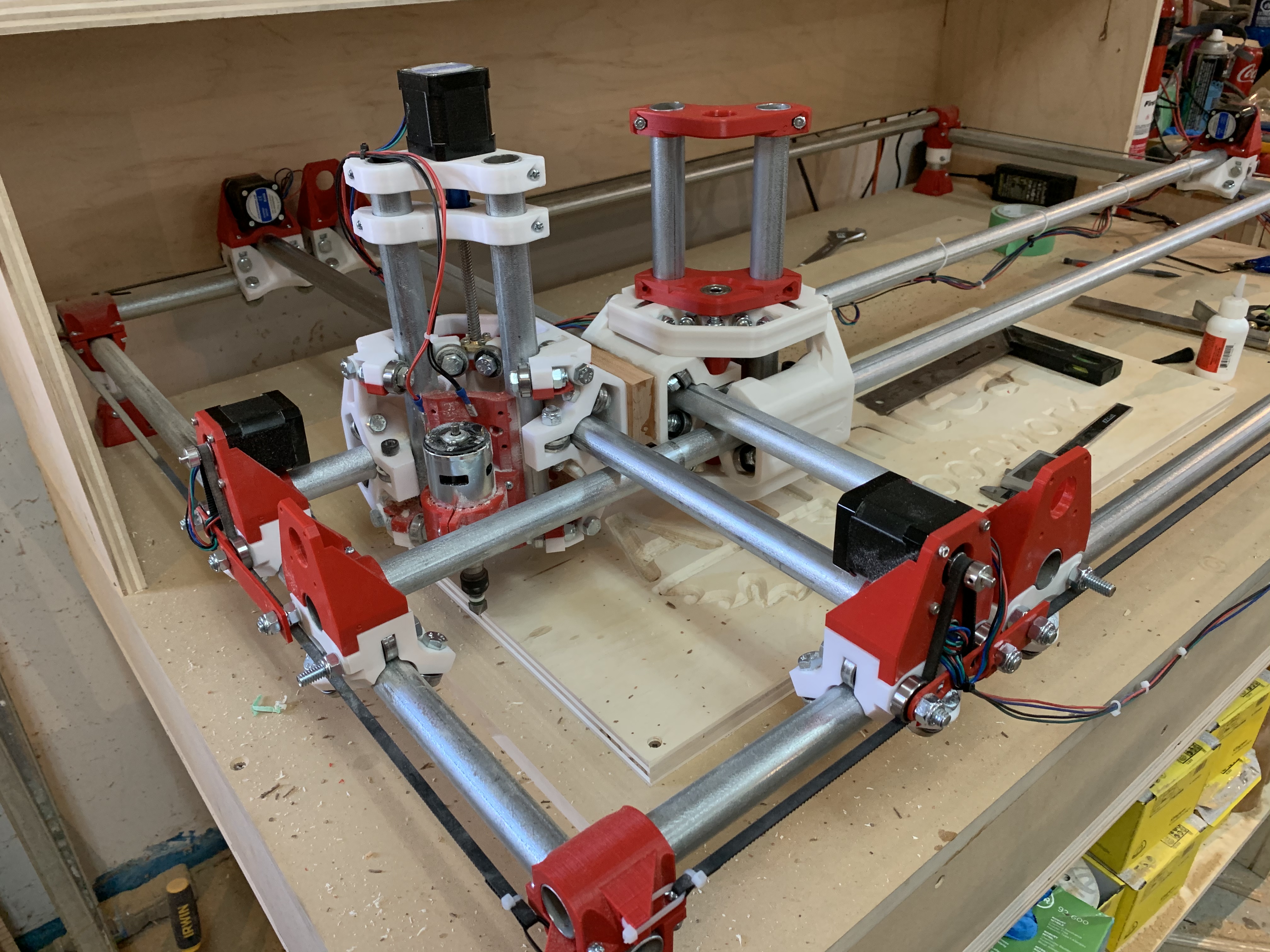
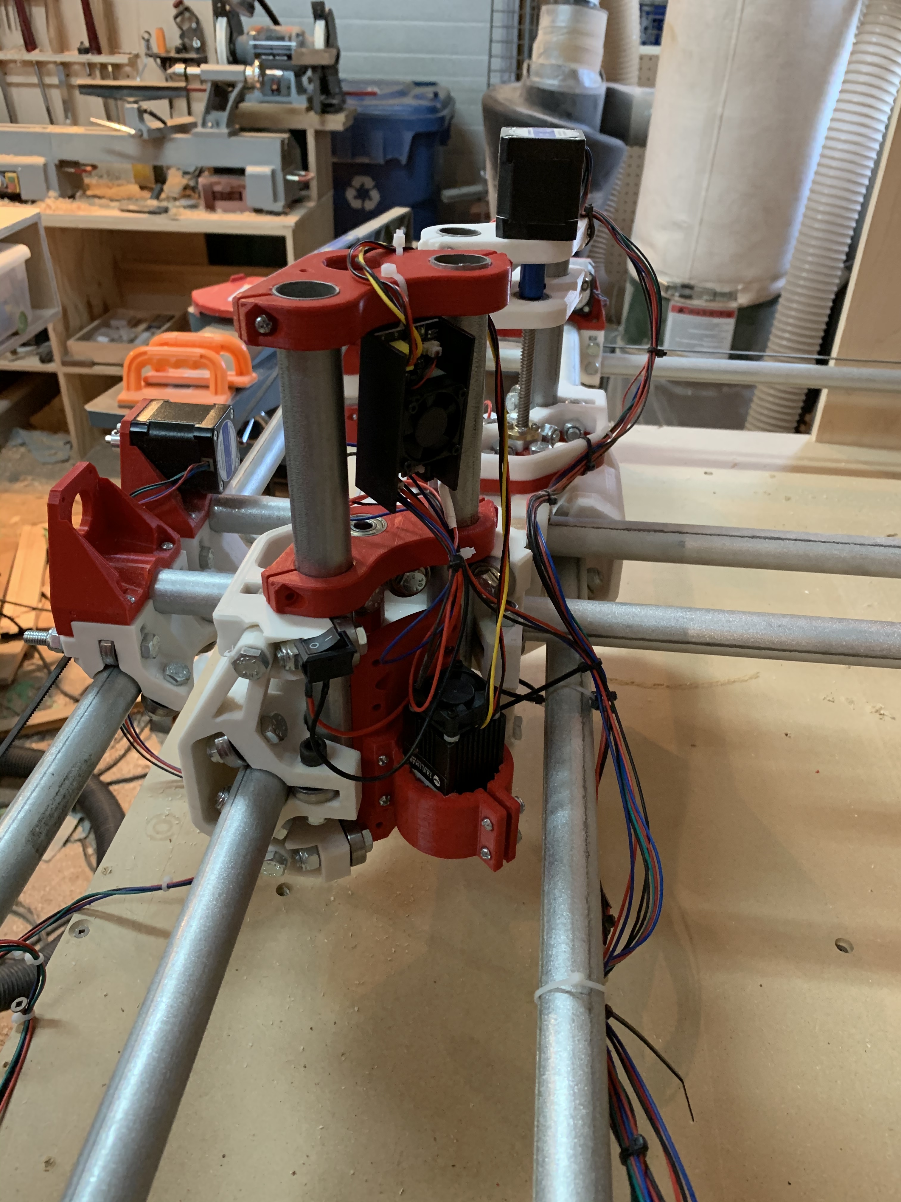
One way to create more rigidity, and fix the need for a dual endstop system, or at least improve squareness would be to have the central be something like a tic tac toe board, with two rails for each axis supporting the spindle/gantry instead of one.
I’ve noticed that each axis deflection is only the strength of its one central pipe. Putting a third stepper in each direction in the gantry could spread the force over all three pipes with minimal bulk. More expense for more steppers though, and possible a bigger power supply
ever thought of using ss shaft? or carbon steel shaft. i’m kinda curious if it would work… well, sorry but im a complete newbie. waiting for my parts:(printed and ordered) so i could start my first build. by the way, if my suggestion, is quite dumb. kindly enlighten me. i am not easily offended. and will accept what people might throw at me, in order to learn. thanks!
That’s cool. If you put a z stepper on the second core you could do two tool operations. You could have a second spindle or a laser or something. The only problem is how to you get that to work in cam. Could use a relay to switch z steppers.
Actually do have a laser on the back side, no need to adjust height once a job has started, if I need to adjust I just move the lower triple tree.
I added switches to the heads so I can Cut the power to the tool not in use