Proper CNC Controller Enclosure?

I’ve been trying to find a place that sells metal enclosures for decent price. I’ve mostly looked at Automation Direct, and they have a lot of nice stuff to choose from, but it’s mostly high budget stuff. I am about ready to shift gears to looking at local metal recyclers, but figured I’d ask you all first…

Does anyone know of some good places online to check for this sort of thing?

I’m leaning towards a (HxWxD) 24x30x8, hopefully with a backpane so I can go crazy with self drillers.

I haven’t used anything that big. But I have used a box for an outdoor sprinkler (irrigation). I also have some electrocal boxes that are meant for small electronic panels. I think I got them at Home depot.

Yeah it’s huge compared to what I’m used to. My buddy who knows plc boxes well is suggesting I give a lot of room for wireways than I normally would. With a vfd, room for external drivers, step down transformer, 3x psus, misc din parts… it would almost be 24x24 without wireways.

Will have a gander at load centers next time I’m at homedepot… maybe there’s something I can hack there.

My electrical panel box for the whole house is that big.

You could also try to do it in more than one box, with holes cut between them. Maybe separate the motion controls from the spindle?

What about using an old PC Tower case (the side access panel type)? You could use the motherboard stand-offs to mount your own backplane. You may be able to find one at a local goodwill or on craigslist.

From years of experience with machinery controls… always go bigger than you think you need (10-20% minimum). It never fails that you will add things or upgrade components of different sizes that don’t fit the original location on the panel. Plus going larger allows room for wireways and terminal strip, which will make future troubleshooting easier.

1 Like

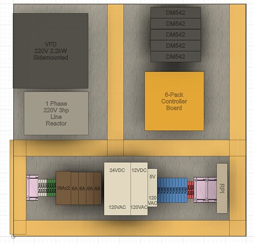
All good ideas guys… and actually this is starting to look like it may well need 2 boxes, or a PC case larger than 24x24. Here is my mockup using everything I can think of at the moment, inside a 24x24 box with 1.5" wide wireways (actual layout is 21x21 to fit on the backplane):

I want to keep the HV wiring and components separated from LV, and high current separated from signals… preferrably HV stuff on bottom. So this is far from an optimized layout, but it shows how cramped it’s getting. Note that all the components on top are DIN rail mount, and everything on bottom is surface mounted. The pi of course can also be din mounted. The 6-pack takes up a lot of area, but can’t really be mounted any other orientation without making it a royal PITA to work on. It probably could also use another inch of padding all around to give room for ferrules and a USB port. Pi has room for USB/HDMI/power as shown.

The VFD is shown mounted to the backplane, taking up a 5x7 inch rectangle with 7" depth. It can also be mounted to the side, which would make it a 7x7 square with 5" depth. The VFD is the deepest component whether I mount on the back or side. So how it mounts will determine the required depth inside the box.

I haven’t researched a whole lot as I have been away from my PC the past week. I’ve seen a new steel 24x24x8 box with backplane that would cost about $140 brand new at Homedepot ouch. A pair of 12x12x8’s would cost the same, and give me a lot less room to work with.

Any suggestions regarding layout, or additional advice on enclosures is much appreciated. It is normally my style to cram things in a lot more than this… like a 16x16x8 doing it “my way” without wireways or room to work, lol. However, I do want room to grow, and would appreciate having something that looks good and is easy to work on (worth $140 to me anyways).

[edit: More info… the cluster of DIN to the left is all low volt (fuses from PSU and relays, signal buses, relays), DINS to the right are all HV stuff (buses, breakers, and PSUs). Of course, the transformer and VFD are also HV items. There’s no main breaker in there yet either… was considering adding an external toggle for the 220V feed instead, as the breaker in my home load center together with the PSU/VFD breakers seem adequate for safety/convenience. I may also just run a separate 120V line so I can keep the pi always on without the transformer. In this case, the transformer may not even be needed.]

If you’re going to put it all in one box, then I’d recommend locating the transformer and vfd up at the top of the panel. They will get warm and you really don’t want anything above them getting baked. You will need some sort of cabinet cooling. Add a disconnect switch rated for 220v. It is bad practice to have multiple power feeds into one box. Don’t forget propper fusing for the transformer and vfd. That will take up a lot of room you have not accounted for on your panel. If i read correctly, your planning on relying on the breaker in your service panel? I’ll just say, please don’t do that…

1 Like

OK I am going to go ahead and do this ‘by the book’ as you recommend. My local buddy who also has setup many industrial controllers said the same things regarding fuses. He also recommended sticking to the transformer and single 220V feed. I know better really, and sometimes I take risks I shouldn’t. That’s matching advice from 2 different experts, which I can’t just ignore.

I already have and planned on using separate breakers for the VFD and each of the PSU’s (DIN breakers that go inside the box as shown above). Do you suggest I use fuses instead of breakers there? I bought 10x 5mm glass fuse holders to individually protect the low volt devices (4mm^2, but probably shouldn’t pass 10A as they’re cheap chinese fuse holders). So I have enough extra holders if they would work, or was is something else I should be using here? I’ll add another fuse (or breaker) in front of the transformer, so as not to rely on the 30A service panel breaker. I have 10awg from panel to the outlet near the cnc, but currently my pigtail from the box is just 12awg… I will up that to 10awg to be safe.

Also, the switch I got to disconnect 220V is a Leviton 30A 2-pole industrial toggle. My buddy mentioned something about a “contactor” being the best way to do it if the load is inductive (ie the transformer). You think the equipment I have would wear out the toggle switch too fast and I should use a contactor instead? It would add even more complexity/expense, but since I want to “do it right” this time I’m all ears.

Was thinking this contactor would work, and just use the 2-pole switch to fire the 220VAC coil:
https://www.automationdirect.com/adc/shopping/catalog/motor_controls/iec_magnetic_contactors/iec_miniature_contactors/cwc025-00-30v24

or …<1/2 the price, but 1/8 the MTBF of the one above (and blades to poke with fingers):
https://www.automationdirect.com/adc/shopping/catalog/motor_controls/definite_purpose_contactors/definite_purpose_contactors_(25_to_60_amp)/wdp25-2l-230

Also, I think I have a better layout with the VFD on top. I’ll post another layout image after I get everything else in there and cleaned up. I did plan on installing some fans+filters for clean positive pressure cooling. I’ll probably put 2x120mm fans+filters low, and a baffled vent on top. For circulation inside, there’s the VFD fan, a 60mm fan for the pi, and an 80mm for the stepper drivers.

[edit: Changed the title of this thread, since we’re going deeper than sourcing a box.]

I was thinking about my 120VAC needs… I am currently using just a relay to switch 120V for a small air pump for laser air assist, and an 8A dust collector blower (plan on swapping the relay with a contactor). That’s going to put me well into 1kVA range if I use a transformer for it all. Would it be OK if I swap the 10awg for one with 4-wires, and use neutral to get 120V to these devices? How important is having the isolated 120V that a transformer provides vs using a neutral? If I end up needing a transformer for everything, it’s going to be an encapsulated one mounted outside the controller box (too big to fit >500VA exposed core inside I think). At that point, I’ll probably rethink using 2 boxes… one for the HV stuff (transformer, vfd, breakers, psu’s, contactors, etc), the other for the controller and rest of the LV stuff (relays, fuses, drivers, etc).

Fuses or breakers are up to you, but make sure they are sized properly fast/slow acting or correct trip curve for breakers. The 220 mains need to go through a proper disconnect switch. Make sure you run a ground wire with the 220 mains. Both legs need to have either a fuse or breaker. Turning on disconnect powers up the transformer. An on/off switch on the secondary from the transformer power to act as controls power on/off switch. That switch would turn on the 120vac from the transformer to power up the power supplies etc. Make sure to ground neutral off the secondary side of the transformer. Obviously, each of the devices have propper fuses or breakers. I probably put you to sleep already. You can send a sketch and i could mark it up for you.

As far as the dust collector, you can use a relay controlled by the cnc panel to switch the power supply for the dust collector keeping power seperate. The relay would work as a remote on/off switch.

OK I put more time into planning it out, and decided to do it this way. I’ll swap the 3-wire 10awg with 4-wire, and use that to supply 120VAC. One pole of 120 to the vacuum, the second pole to the PSU’s (both poles to VFD of course). Using the neutrals instead of a transformer will take less room, however I understand I may end up needing an input line reactor for the VFD if I have noise issues. I left room for it in the new layout.

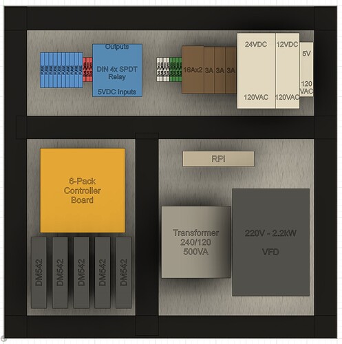
Let me know what you think of the layout. I did it so I can have all 110/220 on one side, and low volt on the other.

I think I’ve got all the breakers and fuses as well. All 110/220 will be on breakers, with a main switch disconnect; 16Ax2 for the VFD, 16A for the vacuum (controlled via relay), 6A for the 24V psu, 6A for the 12V psu, and 2A for the 5V psu. Fuses will be 5x4A for each of the 5 drivers (tmc2209 @2A/24V), 5A for the 12V/40W laser, 2A for the 12V mist solenoid and air valve, 5A for the 12V spindle fans and water pump, 5A for the 5V pi, and 2A for the 12V enclosure fans. I got an assortment of terminals, including dk4n type to handle the10awg wires. I also have a cheap 40A ssr I thought of using for the vacuum, but I figured there’s no reason to change out the 5V relay that has worked for a while without issues. I considered adding spindle fuses, but there isn’t much room left for something that may not be necessary.

I’m confused. What are you running? Spindle with vfd or laser, or both? If you’re that concerned about noise to add a reactor, (motor leads probably not long enough to require reactor) then a transformer will help isolate from any incoming line noise. Also, to help prevent noise issues, before going overboard, make sure to ground the negative sides of the 24, 12 and 5v power supplies. If i read correctly, you are only keeping the 5v ps for a relay to turn on vacuum? Why not use a 24vdc coil relay off the 24vps and eliminate the 5vps?

Good questions… yes I am running both a vfd and a laser. It is configured for an easy tool change, but has potential to run both automatically if I made a mount that holds both. The 5v is to power an always on rpi3b and 7” ips screen only. The 5v for relays actually comes from an switcher on my controller board. Also, not sure you meant bonding the dc negative to earth, but the way the laser and stepper drivers are designed, I have no choice but to make the 3 psus common ground at least.

Tie the dc negatives to ground. Run a wire from each of the negatives to your grounding point. Run individual runs, do not daisy chain them. It sounds counterintuitive, but helps reduce possible noise. Plus, it gi es you the added benefit of testing your dc circuits to ground i stead of back to dc negative. 9x out of 10 if there is a noise issue in a new piece of equipment here, i normally find power supply ungrounded. Granted, there are a few times you don’t want to ground dc ps, but what you’re doing is not one of those cases.

I had missed the 5v powere your pi… makes sense now.

Might want to look into a contactor to disconnect power to vfd when not using spindle. . Could use 24vdc coil and a switch from 24vdc ps. Just use a snubber across coil to prevent voltage spikes

Roger that… I will swap out my black terminals with green ground the dc-.

I was not planning to daisy-chain anything, other than using the clips that come with the terminals. Makes sense regarding noise path and induction. It’s also not ideal for the added resistance. In my work (home construction), resistance of series connections can often cause problems. NEC allows daisy chaining through outlet tabs, push connectors, etc, which have much higher resistance vs wire nuts and pigtails. I have some air compressors that will trip breakers if plugged in away from the panel on a circuit that was wired this way. So I always use pigtails in homes… and “start to end” wires on my DIY stuff.

Good thought adding a snubber on AC coils! Using mostly DC coils my entire life, I totally forgot about that. I have an assortment of safety snubbers from a previous project that may work; got several values to try on an arduino/relay/inductive motor project, which had random logic errors caused by spikes when the motor switched off at the wrong part of the sine wave.

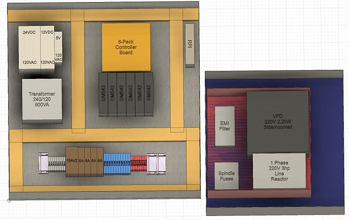
Also, adding that VFD contactor may not be a big deal with the latest changes to my plan (and yeah 24v is fine… much easier to find). I had more discussions with my industrial buddy, and came to the conclusions that I really just need to use 2 boxes, including a 24x24. So here is what I have now using 24x24x8 and 16x16x8:

Note that’s a 3-phase output filter, not 1ph line reactor. Also the transformer won’t be there as I’m using 4-wire. This obviously gives a clean layout that is easy to work on and upgrade. Note I included 2 options for the VFD box, red is 12x12 and blue is 16x16. Only $25 more for a 16x16, but saving space would be nice if you think 12x12 is OK there (I will properly address airflow to vfd in either case).

I did have some what I feel were silly arguments with my buddy over placement of parts on this. He said breakers and fuses should always go on top left away from other stuff, and only terminals for wire entry (or devices that wire direct like spindle fuses) should be on bottom. When I worked out wiring for this, I just didn’t like all the extra length of wire, and even worse having signals parallel to power for longer than necessary.

I get that the average joe industrial operator may expect fuses in a certain spot, but for myself I always follow power wires in and go from there. So breakers on bottom next to HV terminals seemed logical. Also, my layout makes it easy to keep signals and power separated better. I also like that (for me anyways), there is an obvious separation between hazardous areas and safe areas. Having breakers and fuses together would mean HV hazard changing fuses.

What are your thoughts on this?
I’ll dig through your post in a bit, a bit lengthy. I just wanted to clarify that you add a ground to the dc negative, not replace the negative wire. :wink:

Yes I understand, but I was not being clear regarding grounding. What I mean is using all the same wires for dc negative, but the swap the terminal blocks for grounding blocks. This way they get grounded with no additional wires.

Haven’t forgotten about you. Just been beyond busy…