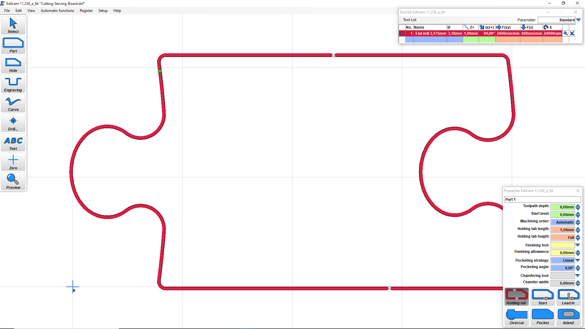
When you create your tool paths are you cutting on the line, or outside the line? If you are cutting on the line (“Engrave” in Estlcam), your gap will be equal to the 1mm designed gap, plus your tool diameter, all the way around. If you cut outside the line (“Part” in Estlcam), you should get the correct fit.
It is also possible that the tool size in your CAM is smaller than your actual tool size.
Just to make sure, your issue is that there is too large of a gap between the pieces, yes? Have you scaled the drawing at all? Is the over-all width of the piece correct, or is is undersized as well?
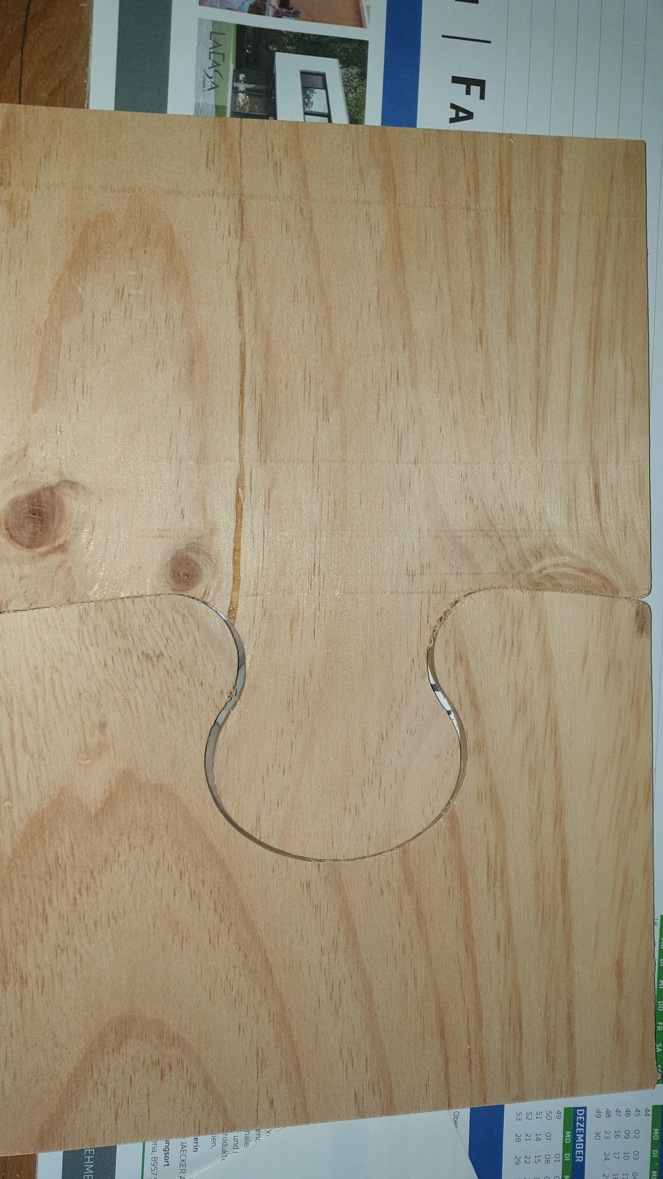
That is a funny looking gap. Both cuts should be on the outside of the line. That looks a lot like you tried to cut one piece into two, and that will always leave a kerf the width of your endmill.
That has to be two separate cuts on two separate pieces. Both on the outside of the path.
@Strider_Matic
The Gap between the pieces is too large, yes. ( First Picture)
I dont think i scaled anything. I have just took the dxf und imported it in Estlcam.
The PDF drawing fits perfectly.
I Have to checked if it is undersized.
@vicious1
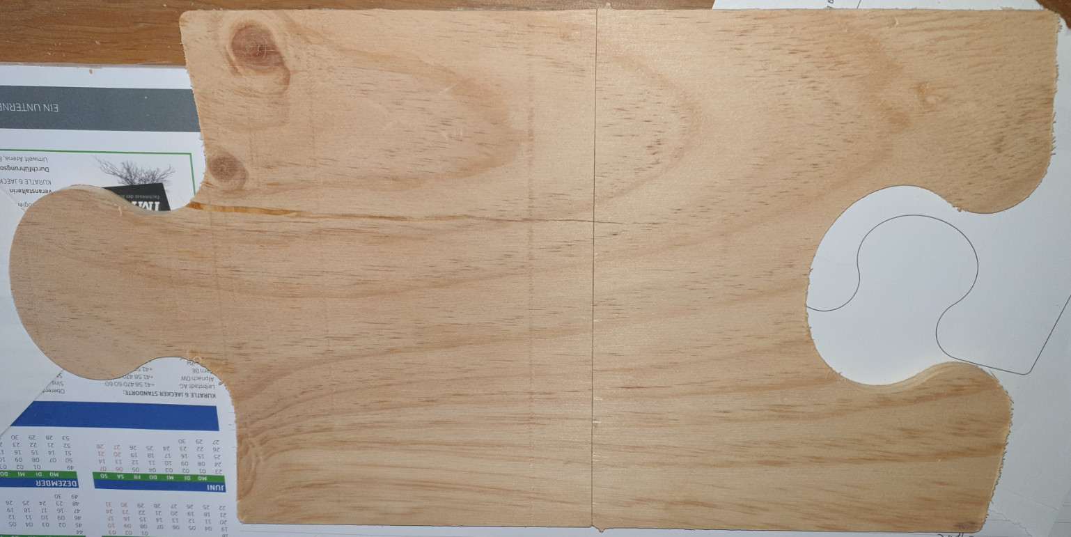
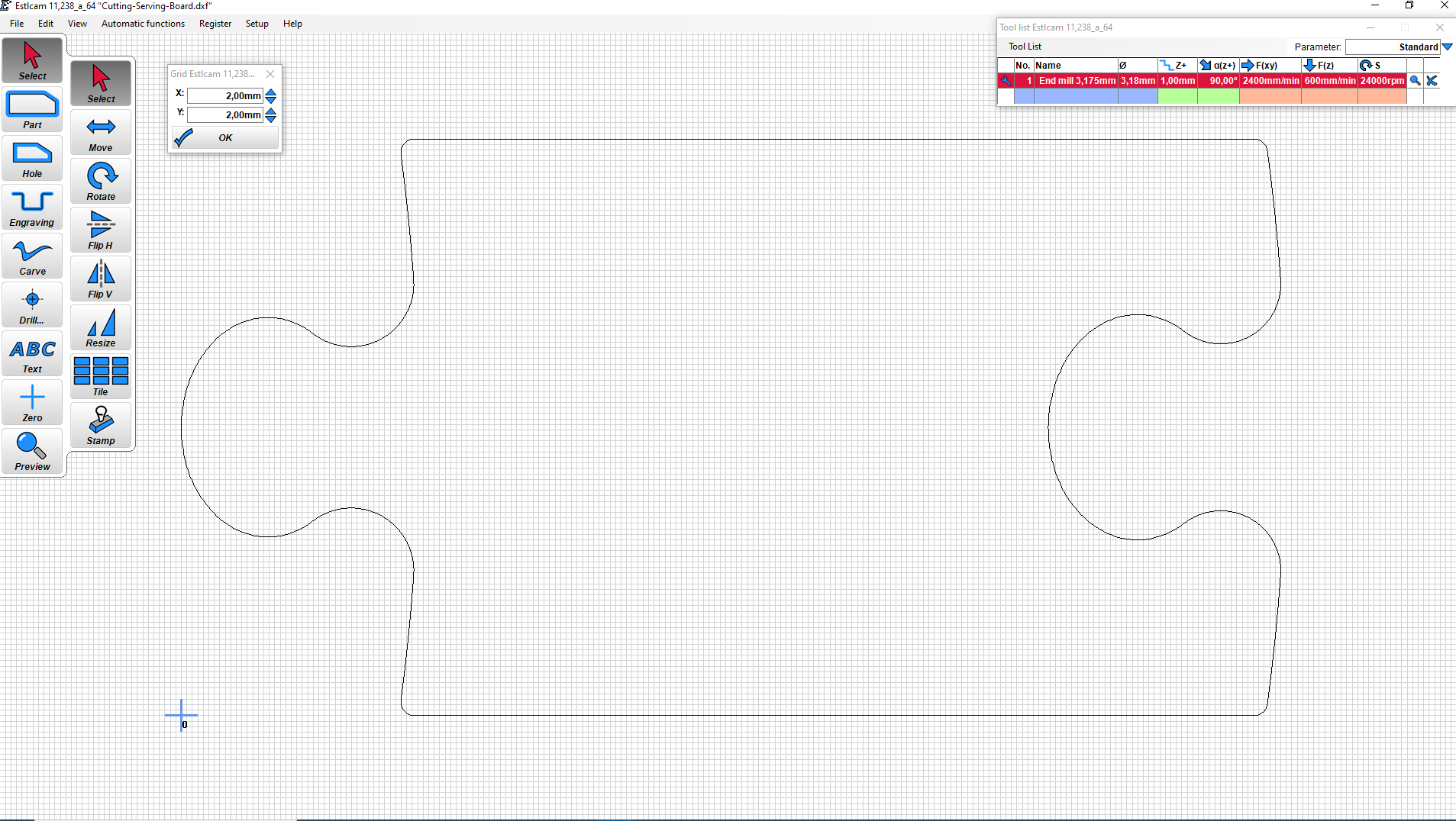
This actually just one piece cut in half to see if it fits ( Picture Puzzle1.Png ) . It is one time cut.
That’s pretty weird. The only other thing I can think of is that the gap is bigger in the dxf then the description on Zenziwerken says. I guess a work-around could be setting the tool size a little larger in Estlcam to compensate. I know it’s not the right way, but it should get you there.
Using that grid pic I am seeing the tab is at least 1-1.5mm smaller, on one side alone. If you want a tighter fit cheating your tool size will be a little guess and check, or CAD one up yourself with the tolerance you want.