Hello, using the dual endstop cable how is suppose to attach the cable to the Limit Switch
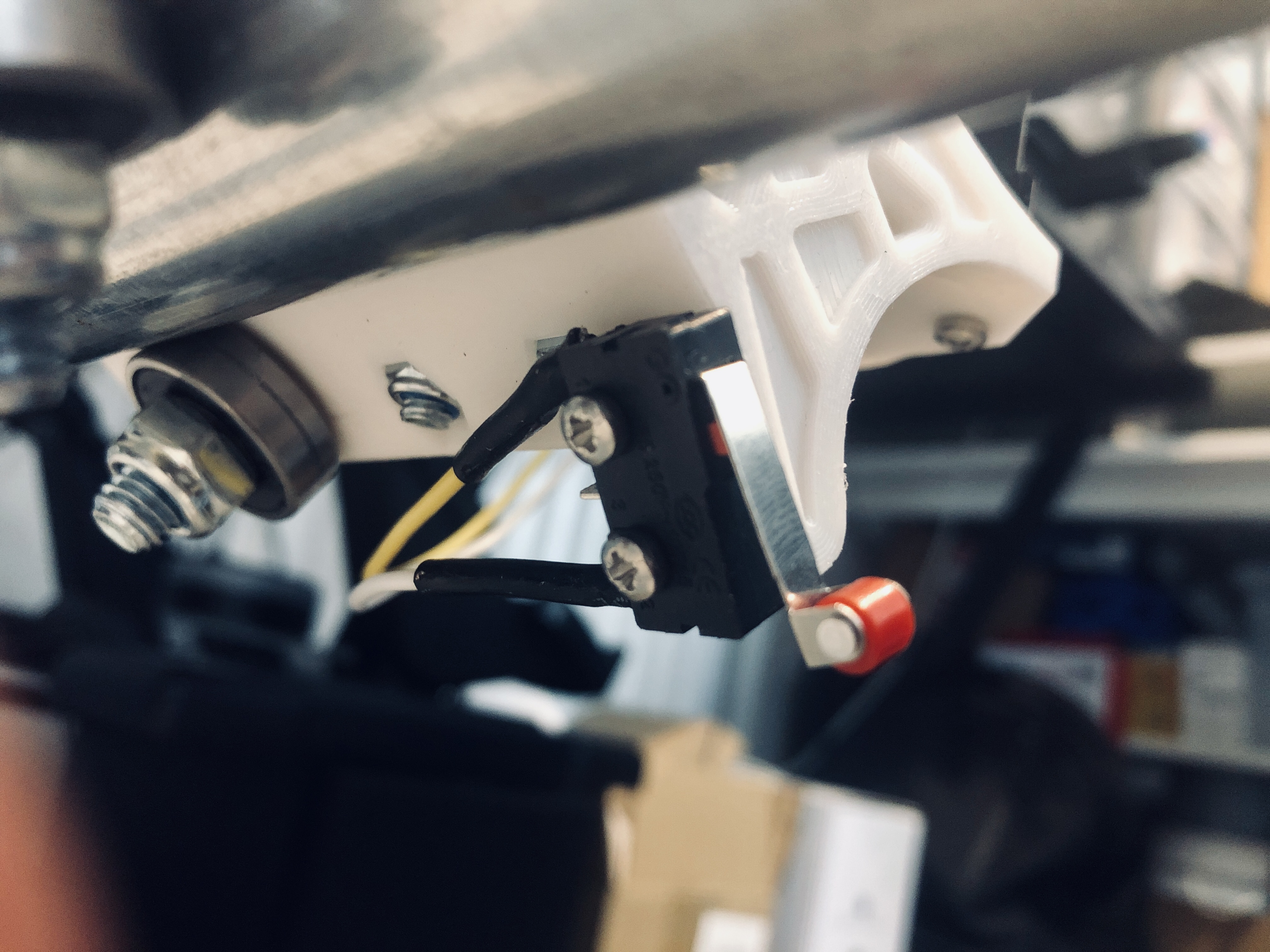
I used the roller style switch. I then just used 22awg wire, soldered it and covered with heat shrink.
1 Like
Alex,
I also routed the endstop wires in the same bundle as the stepper motor on that side of the machine.
Mike
There is no right way to attach the wires to the switch. My Rambo board came with wires with spade connectors at the end that just slide on the limit switch terminals. Some people solder them. The firmware that V1 maintains expects the switches to be wired normally closed , so you need to pick the correct terminals on the switch. Polarity does not matter, so it does not matter which wire is connected to the switch, nor how it is plugged into the board. Just be sure to use the ‘s’ and ‘-’ pins and avoid the ‘+’ pin.
Thanks you for your suggestion
If y ou got the wiring kit, it terminates with a 2 pin male Dupont connector, so you would need to attach a 2 pin female Dupont connector to the switch. If you have spade terminals that fit your switch, that’s easy enough, or solder them. You could probably solder to the male pins on the Dupont connectors if that’s what you’ve got.
I’ve said it before, but by convention, I connect the “S” pin to the common pin of the switch. With that setup, if you did connect the (+) pin to normally open, it should do no damage to anything, but is not necessary with the pullup resistors enabled, and as with anything else unnecessary is best avoided.