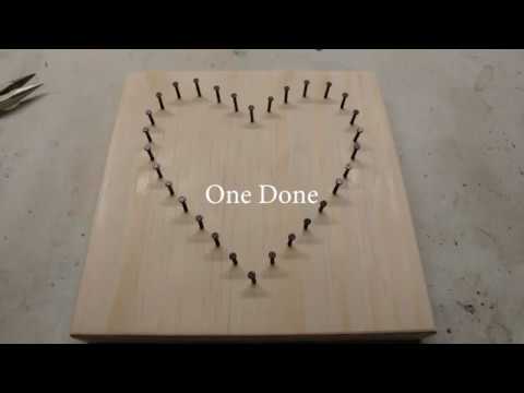
Yea, the key features are definitely more important than the even spacing.
Love this idea! Not sure how to go about that though lol.
I did some exploration of something similar for someone on another topic. He wanted to paint dots along paths to create Australian Aboriginal art. I found a couple of methods. In Fusion 360, you can create paths and set points that are confined to the path but can be moved along the path until you get exactly the placement you want. From there, you can turn all the points into holes in a single command, and in the CAM side, you can create a drilling job from the holes in a single command. There is a free/personal version of Fusion 360, but the learning curve can be steep, but for this task, you only would need to learn a very limited about of the app.
One thing you will need to work out is the actual drilling. Endmills and high RPM routers/spindles are not made for drilling holes. They will do the job, but it is hard on the endmills. You probably want a variable speed router so you can slow things down, plus there are likely drill bits with geometries designed for a CNC.
Edit: I did some additional research on drilling with the CNC this morning. A variable speed router or spindle dialed down to a minimal RPM (10K) was beneficial. For solid wood, an upcut endmill worked well. For plywood, a drill bit was recommended. In plywood, endmills tended to get gummed up by the glue layers. For both types of drilling, a “pecking” setting was recommended to keep the hole clear.
That’s pretty impressive. There’s no way that she would ever give up the stringing part lol.
I’ve played around (very little) with Estlcam but I’m assuming if you’re telling me to use fusion because Estlcam can do what I need it to?
He’s suggesting using fusion for the pattern. Using it for CAM is a different operation (at least that’s what I am reading). Estlcam could work if you have the pattern of holes in a dxf. It can’t creat the pattern, unless you do it all manually.
Ah ok, thanks for the clarification.
Fusion 360 does support the CAM, and while there is a lot of daunting interface in the CAM section of Fusion, you only need to learn a very small piece to get your job done.
I just ran a quick test, and DXF files exported from Fusion 360 don’t contain authored points. In order to use Fusion 360 for the authoring and EstlCAM for the CAM, I think you would need to author all the points as circles in fusion 360 in order to get the center point in the DXF for authoring the drilling. This would be a major amount of additional work in Fusion 360. And while I’m not sure (especially since I don’t use EstlCAM), in my brief test, it appeared that you would need to select all the points individually in EstlCAM for drilling. I didn’t see a batch way to select the drilling points.
If you interested, I’d be glad to provide a sample Fusion 360 file and the steps used to create it.
I’d love a sample file. I downloaded fusion today and started watching some videos on basic functionality.
You don’t need much Fusion. I would watch videos on the following topics:
- General user interface
- Inserting and calibrating a Canvas (reference photo)
- Basic sketching
- Sketching constraints (you won’t use them much, but they are auto-applied and you have to understand them to delete them to get what you want).
- Extrusion (Solid workspace)
- Holes (Solid workspace)
- CAM tutorial.
For the CAM tutorial, this one is basic and pretty understandable.
At some point, you will need a postprocessor to generate g-code. See this topic for the Guffy one that has generously been upgraded/fixed by Don Gamble. I’ll create the example project this evening.
Bart’s video was great: thanks for sharing!
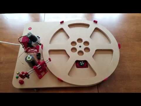
Also worth watching: in the YouTube queue after Bart’s video was a delightfully over-engineered CNC system for both driving nails in custom patterns, then a stringing system with modular thread spools so multi-colour art was possible.
String Art Machine by knezuld11
I have a variable speed rotary dremel tool with speeds from 15000 to 35000. Will this work? If so, is there a specific mount I need to get? or I can go get the Dewalt 660
I’m of a mixed mind here. I’ve seen people on this forum complain about the longevity of using a Dremel for CNC routing, and 15000 is a bit fast for drilling. On the other hand, you already have it, and Dremel sells a set of bits in the kind of sizes you need that probably have a geometry that works well with a Dremel. It wouldn’t hurt to try the Dremel with the understanding that you may at the very least go through a set of brushes quickly.
As for a mount, I doubt there is a Primo mount for your Dremel. There are Dremel mounts for the Burly on Thingiverse (different Dremel tools use different mounts). By printing the Burly Mounting Plate and the Burly Nut Traps, you can attach a Burly mount to a Primo. With the model of Dremel and some measurements off your Dremel, I can help you sort out the Thingiverse mounts.
If drilling patterns is going to be your primary task with your CNC, then I’d recommend the Makita RT0701C instead of the DW660. It has a built-in speed control with a low rpm setting of just 10,000k. You will want to purchase a 1/8" collet for the Makita.
There are a lot of different ways of making the same thing in Fusion 360. I remember watching a video where the author created a cube ten different ways. I’m going to outline one pathway/recipe to go from a design image to drilling holes. I’m skipping some details that may require you to do a bit of research (or ask me) in order to keep what will already be a long post from becoming a novel.
Before you begin, you need to make sure of one setting in Fusion 360. Click on your account icon (upper right), select Preferences, select General, make sure “Default modeling orientation” is set to “Z up.”
Steps:
- Create a sketch on the Top plane.
- Create a rectangle the size you want your stock. Sizing can be done at the time of creation or by adding dimensions. Finish the sketch. Note that your actual stock can be bigger than this rectangle, so you don’t have to be precise.
- Insert Canvas (image) of your design. It goes on the Top plane, and use the rectangle for step #2 to size and position your image.
- Create a second sketch the Top plane
- Using your image as reference, create any splines, lines, arcs, etc. that you want to use to constrain/align your points.
- Put Points on the lines to match your design or vision. Points will stick to the lines such that they can be repositioned along the lines but cannot be removed from the lines. Finish the Sketch.
- Selecting the rectangle from Step #2, use the Solid/Extrude command with a negative value to create a solid that represents your stock. The negative value will extrude downward, leaving your sketches positioned on the top of your stock.
- Select all the points you want to be holes for nails, and use the Solid/Hole command to make the holes. It will be easiest to select all the points and then do a Ctrl-Click to remove any points that you don’t want to be holes. The “Placement” parameter in the Holes commands allows you to create holes for all the points at one time.
- In the Manufacture workspace, create a new “Setup.” Everything will be the default in that Setup but one item. In the second tab you will want “Stock Offset Mode” to be “No Additional Stock.”
- Select Drilling/Drill. You need to select a drill bit in the first tab, which you will have had to add to the Library at some point. In the second tab you will set Hole Mode to “Diameter Range” and specify a range that included the diameter of your holes. In the third tab you may want to set “Bottom height” to control the depth of your drilling. For example if you have 12mm plywood and want to drill down 8mm, you would set “Bottom height” to “Hole Top” with an Offset of -8. On the last tab, try a “Cycle type” of “Chip breaking” to start.
- Simulate to verify and Post Process to generate the g-code.
Advanced stuff:
You can reduce the amount of work making these designs while at the same time increasing the precision by using sketch tools like Mirror, Circular Pattern, Rectangular Pattern, etc.
You can create holes evenly spaced along a path/spline/line/curve using the Pattern on Path command in the Solid workspace.
I’ve attached a ZIP file with two Fusion 360 files inside. “String Art B” is an example of the steps above. “String Art Starfish” is an example using Pattern on Path to create over 200 holes, evenly space and without measuring or hand placement, in just a few minutes.
StringArt.zip (529.8 KB)
Fusion 360 is a parametric modeling tool, so you can go back and edit any of the steps along the way and the changes will propagate through the design.
Yes that’s pretty much it at a basic level.
I couldn’t figure out a way of getting the nails into the wood any easier.
I used the dewalt to pre-drill the holes undersized. It didn’t take long to hold the nails with needle-nose pliers and tap them in with a hammer. Usually only one hit to get the nail seated in the hole.
Wow. There are a lot of neat engineering solutions in there. Some of them aren’t even that obvious. Like the tape to start the string, or the automatic tool changer or string cutter. But also, then it’s putting in the nails, the gantry is too hulky behind the nail. So it has to be programmed to only work from the front to back, or it will collide with the already placed nails. Very neat.
The table I have is 5x3’ Using the calculator I selected the Makita tool, a 24x24" workspace which gives me a total machine footprint of x=38.75" y=39", which is 2" larger than my table. So I need to make my work space a bit smaller like 22"?
The EMT I bought is 1" OD which means I will need the 25.4mm printed parts, along with the Series wiring, Rambo control board, Makita tool mount and 1 extra meter of belt. (and maybe the LCD screen)
Drill bit vs Endmill advice?
I think that covers the hardware unless I’m missing something else.

