I need to contain an 8mm diameter rod in a linear direction while allowing it to rotate freely.
The rotation will be slow and the lateral forces on the rod will be fairly minimal, but it must be able to withstand a constant linear force of, say 10 lbs.
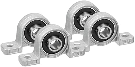
These look like they might fit the bill, but I can’t find any info on how much linear resistance they might have. The description says the bearing can be easily replaced, which tells me it is most likely just a pressure fit. What I’m hoping is that the bearing slides in one side, but cannot slide out the other. This would be fine for my purpose, because the linear force will only be coming from one direction.It isn’t easily apparent that this is the case from looking at the pictures. The force would be distributed over at least 2 of these bearings (possibly 4 since that’s the way they’re packaged).
So, anyone have any experience with these? Would these work? If not, what would?
I would appreciate any input.
Edit: Google search didn’t help me much, but YouTube did. It appears these are not a press-fit. The inside of the mount and the outside of the bearing are somewhat doughnut-shaped, and the bearing has to be rotated 90 degrees to the mount in order to remove it. So, the question is not so much if the bearing would be forced out of the mount, but how much linear resistance does the bearing itself provide.
I haven’t used those in particular, but can’t you just 3D print some retaining clips to keep the bearings from being able to slide out? As long as the clips don’t touch the rod or the inner bearing race, they should be able to manage the job…
That’s a great idea to keep the bearings in place, if they were a pressure fit. I was editing my original post probably at the same time you were responding. The edit was that the entire bearing would not be pushed out, due to it’s shape, but I’m wondering now if the bearing structure itself can withstand the linear force. (I have no idea how they are constructed).
Yes, the grub screws would definitely keep the rod from sliding through the bearing. I guess my question is whether the bearings are designed to handle a load in the linear direction. For example, if the rod was held vertical by the bearing and you placed 10 lbs on it, would it operate without failing.
I could see the locking collar as a failsafe for the bearing, but in order for it to help handle the force, it would actually have to ride against something solid (other than the bearing). This would introduce friction that I don’t want.
I will just show you guys what I’m working on so you see the whole picture.
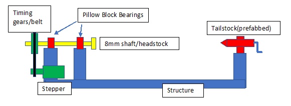
I want to build a LowRider “Lathe” attachment. It would look something like this:
You see the use of the pillow block bearings here. The force against them would be however much it takes to hold a piece of wood between the stocks securely. (I just assumed 10 lbs max.)
This assembly would be mostly under the LowRider table at one end. It would be situated so I could park the LowRider directly above the stock (and somehow lock it in place), with the centerline of the stock even with the top of the spoilboard. I would disconnect the “Y” stepper from the LowRider and plug in the stepper from the “Lathe” attachment.(I’ve been looking for a switch that would do this, but so far no luck) I could swap out the gear on the 8mm shaft to be as close in diameter as possible to the stock, and then take care of minor differences in diameter between the gear and the stock in CAD or CAM. The stepper motor would be adjustable up or down to accommodate gears of various diameters. The tailstock assembly would be adjustable side-to-side to accommodate various lengths of stock.
The bearings should handle quite a lot of load, but they may have a bit of axial play. If you always use the tail stock to preload axially then theres no problem.
One alternative would be to preload the two bearings against each other. You just need enough preload to take out the slack, so it won’t significantly add to the rolling resistance. This axial preload should also take out radial play, if there is any.
My gut feel would be that the ability to support axial load should be less than half, but more than 1/10th the capacity for radial loads. I would think an 8mm bearing similar to 608 should support maybe 100 lbs axially without any issue, and 10 lbs sounds very safe to me.
I use a couple of those on my Z-axis on my Maslow CNC on the 8mm threaded rod. I have a plate with a full size router hanging off of it (it’s also supported on the sides by some linear rods). On that, it is sitting mostly vertical and I have not had any failures or the bearing popping out at all…has been almost a year of being set up if that helps to answer your question? I used to have a pic, but can’t find it right now.
I thought of that, but I would somehow have to marry that to a shaft that would allow me to mount timing gears of various sizes. My research down that road didn’t get too far before it looked like the barriers were getting too big.
Also, partly in the spirit of the V1 ethos and partly because of the fact that I’m frugal, I want to keep the cost to a minimum.
I would like to think that others may want to build this and wouldn’t want cost to be a barrier. (I learned that from my buddy, Ryan)
I’d be looking at creating mounts that I could put thrust bearings in on each side with the bearing facing out. Then using a clamp on the rod up against the thrust bearing to keep it from shifting laterally.
Those, along with the collars that Ryan suggested, would probably be the most heavy-duty (and proper) way to do this. Those bearings are pretty wide-open, but the mount could also serve as a dust protector.