I have a Rambo 1.4 and I’d like to control my spindle’s power supply using relay with 5V logic. I don’t see a 5v logic pin on the board. Can I repurpose one of the unused pins and how?
From what I’ve seen on the forum, it is pretty typical to use a 12V relay and one of the fan pins and fan g-codes (M106 and M107). If you want 5V, you can approach the problem two ways. First, you can use an unused pin and M42 g-code to control your spindle. Second, you can reassign one of the fan pins to a 5V pin and use the fan g-codes. To reassign the fan pin, modify pins_RAMBO.h, and then compile and flash the board. M42 does not require a recompile.
As for free 5V pins, see this block:
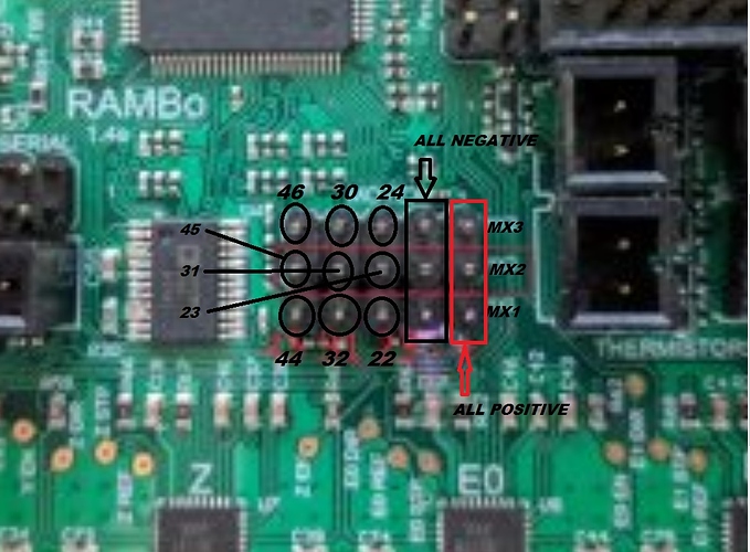
Pin 45 (middle row, left end) is assigned to control the laser in the V1 maintained versions for the Rambo board, but the others pins should be free. Pins 44, 45 and 46 are PWM pins. Pins 30, 31, 32 are not.
2 Likes
Thank you! I’ll give one of these options a try.
BTW: I use one of these and the fan pins on my Rambo for my power switching. It accepts a wide range of input voltages.
Yeah, I saw that before. I’m on the notification list for when they come in. In the interim I’m using this: SparkFun Beefcake Relay Control Kit (Ver. 2.0) - KIT-13815 - SparkFun Electronics
I like you are using that particular relay. I’ve seen others on the forum adding router switching using the cheap relay modules like this. They seem to work, but I’d be uncomfortable using the cheap relay modules with an inductive load like the router.
 Thanks
So I was seeing this on the v1 engineering docs.
When using a laser or a PID controller the Pins on MX2 are available:
45 (PWM) Your laser pin or PID speed. Controlled by
M331 (Laser or PID) Enable, Controlled by
M523 (not assigned yet) Shared with YMAX
Looks like I could use pin 31 and connect my relay to that and control on/off with M04/M05. Question is on the control side of the relay board there is a COM, ctrl, and 5v connections. What from there goes on what on mx2? Which goes to pin 31 which goes to + and/or - on mx2?
Many of the pins on this block are defined in Rambo.h for some use, but runtime logic may not access the pin if that feature is not used. Of the uses defined for this block of pins, the “safest” might be pin 46, which has this define:
#ifndef CASE_LIGHT_PIN
  #define CASE_LIGHT_PIN                      46
#endif
I’m sure many of the other pins would work (including 31), and, to the best of my knowledge, you cannot hurt anything if you were to try them. As for hookup:
- Pin 46 (or 31 or whatever) goes to ctrl
- Any of the pins labeled Negative goes to COM
- Any of the pins labeled Positive goes to 5V
Thank you!!!
It is possible you will have to set the pin state to OUTPUT before you use it. Based on the reference, the syntax should be:
M42 M1 P46
This only needs to be done once at the top of your g-code file. It is entirely possible that it will not need to be done at all considering the other possible use of this pin is a case light.
1 Like
Pin 31 works beautifully. Thank you for your help.
1 Like
You’ve probably discovered this by now, but you’ll probably want to use M3 to turn on the relay and M5 to turn it off M4 allows reverse (counter-clockwise) spindle rotation.
On the relay control side I would start with
- Com to power supply common/ground
- 5V to a 5 volt pin on the Rambo
- Cntrl to pin 31 on the Rambo
Finally, the hot wire from power to the Com relay terminal and the NO terminal out to the to the spindle.
I actually run the relays to hot terminals on regular 120v outlets (I’m in the US) with proper neutrals and grounds then just plug in my spindle/accessory. But I’m comfortable with this kind of thing. In addition to spindle on/off, I’ve got outlets wired to relays on coolant mist and flood pins to eventually control things like air blast and vacuum table.
Thanks for the tip on the gcode commands. I actually did set everything up just like you did. Seems to work great.
1 Like
Finally have time to come back to this. So although sending M03/M04 and M05 commands turns spindle on and off correctly, something weird is going on where any G00/G01 commands are also turning it on. Also when this happens M05 doesn’t turn it off.
The laser pin (assigned to pin 45 by V1), is controlled by both M03/M05 and by the ‘S’ parameter of the G1,G2,G3, and G4 commands. It might be possible to turn off inline support in the firmware, but I believe a better solution is way I indicated above, leave pin 45 for the laser, use pin 31 or 46 and an M42 to turn the pin on and off.
Thank you. As an FYI, I’ve been using pin 31 for this. If I went the route you suggest and use an M42 I’d have to put that in every gcode file I make?
But if I understand what you did correctly, you had to assign pin 31 as the laser/spindle pin in order for the M03/M05 to control it. Assuming that is what you did, that is the root of the issue with G0 and G1 turning the pin on, and if so, setting the laser back to 45 and using M42 should solve your problem.
No. I didn’t assign anything. Here’s what’s in my firmware:
//
// M3/M4/M5 - Spindle/Laser Control
//
#define SPINDLE_LASER_PWM_PIN 45 // Hardware PWM
#define SPINDLE_LASER_ENA_PIN 31 // Pullup!
#define SPINDLE_DIR_PIN 32
Oh I see. The root of the issue is still the same. The laser code is pulling the pin up and down based on the ‘S’ parameter. Try pin 46 and M42. Avoid any of the three pins listed here.