You changed the baud rate and reflashed it, now you have heating errors. Either you changed a lot more than the baud rate or you have the wrong firmware.
1 Like
Ryan, I finally had a chance to reflash the board today and and everything is back to working order including the LCD. Thanks again for the help. I know it can be a be a bummer to have to deal with troubleshooting questions a bunch but I really appreciated it. Just need to print a couple more parts and I’ll be ready to cut.
1 Like
Awesome! Not a bummer when everything works out in the end.
Hello,
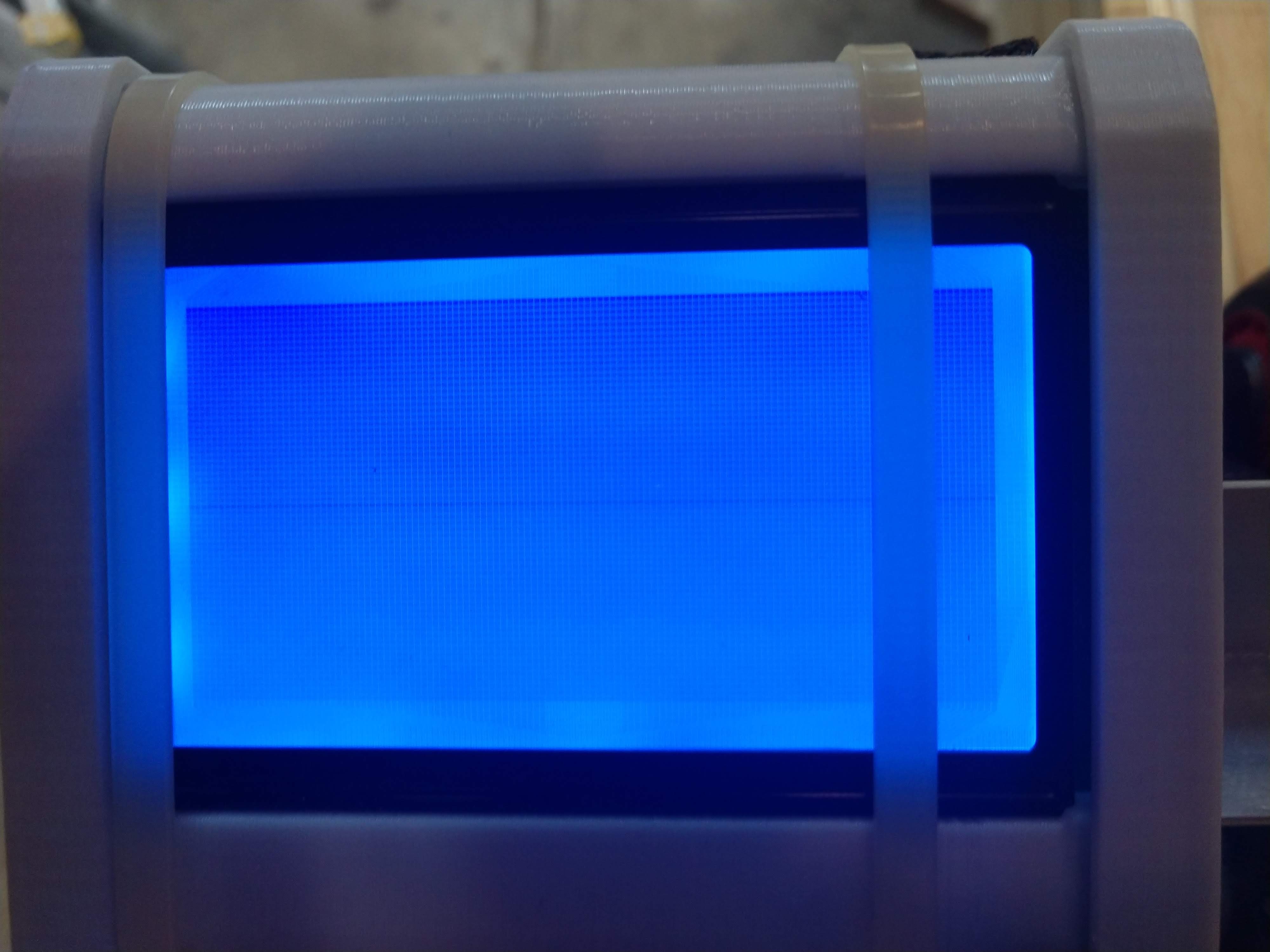
I am having this same problem (I bought the full Rambo kit), and no matter what orientation I put the wires in, I’m left with a solid blue screen. What can I do to fix this? I tried flashing the board (successfully), but that had no effect.
Thanks in advance!
Pictures please!
I finally found this topic when I was having no success with my LCD cables. Finally found an orientation that would work. Just kept trying different ways until they worked.
Fixed! one of the plastic connector was put on the wrong way, so I had to just cut off the tab so it could fit. thanks for your help!
1 Like
Old thread, same problem.
Rambo 1.4 and LCD from V1 and all I get is a blue screen. I tried flipping the LCD cables on the Rambo.
Sorry, can you clarify the final connection setup then? After reading all these different flip flops its very difficult to know what configuration is actually correct. Red ribbons facing what directions, on what boards?
That’s the problem. It’s supposed to be a standard, but it’s not. You just have to flip flop them around until it works. You can’t hurt the screen. Just plug the cables into the board, then do all the flipping on the screen, there’s 4 ways they can be plugged in. If the plugs are soldered on correctly, there’s only 2.
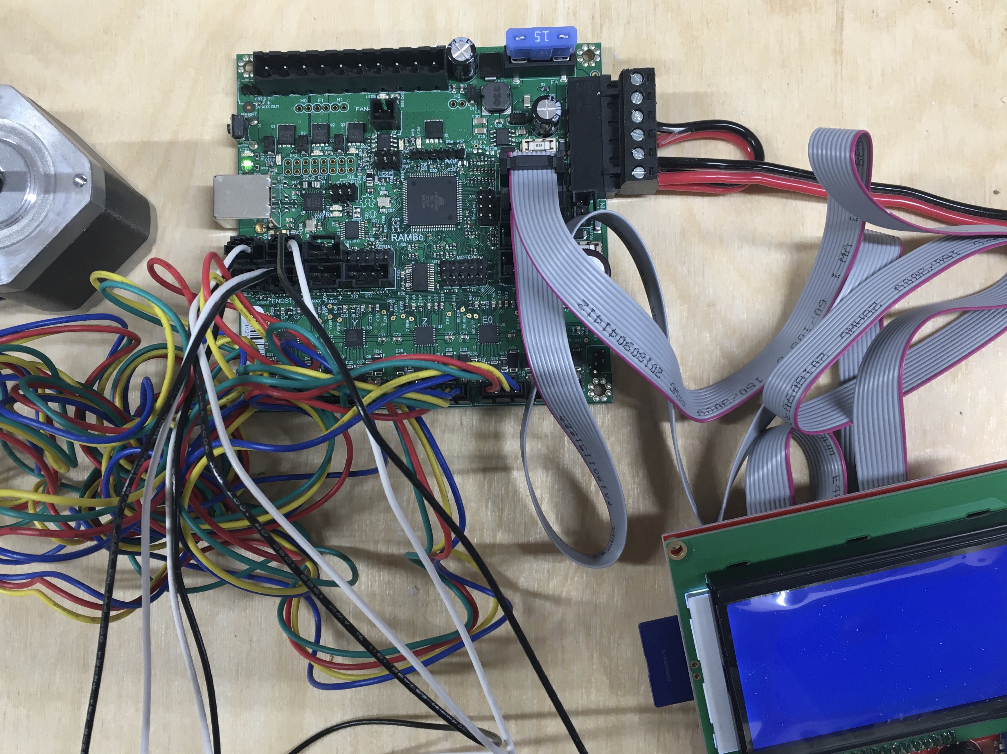
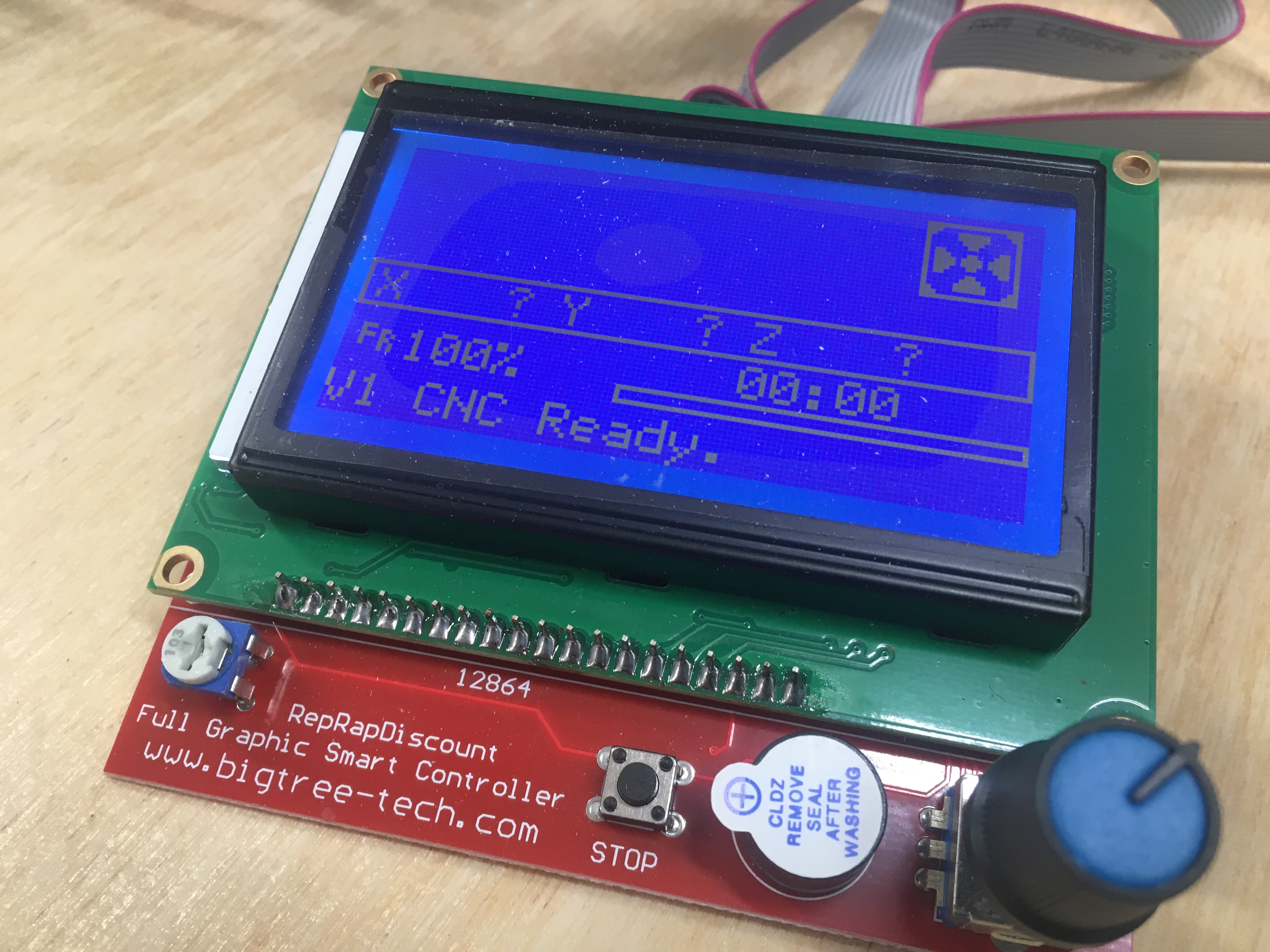
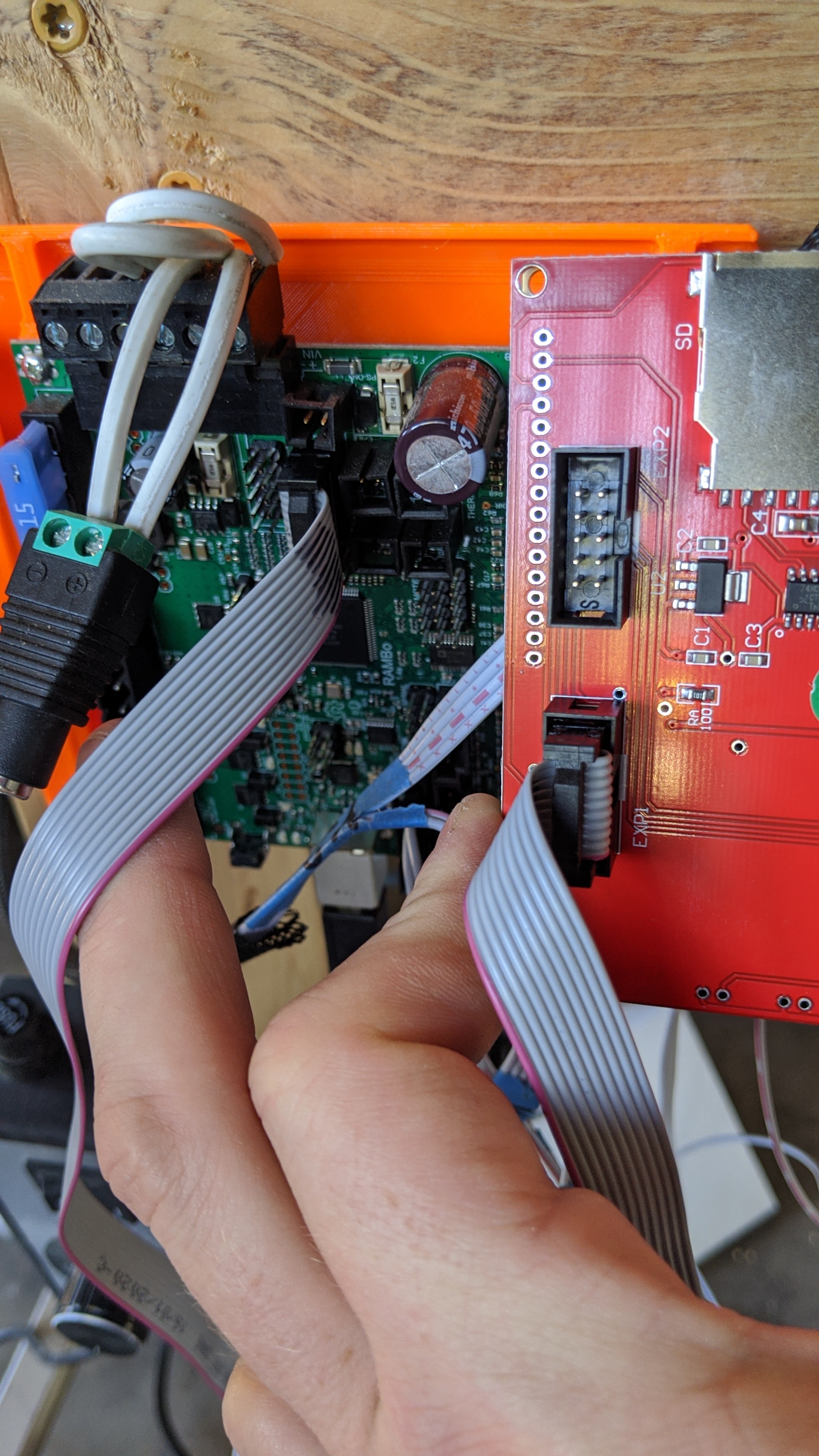
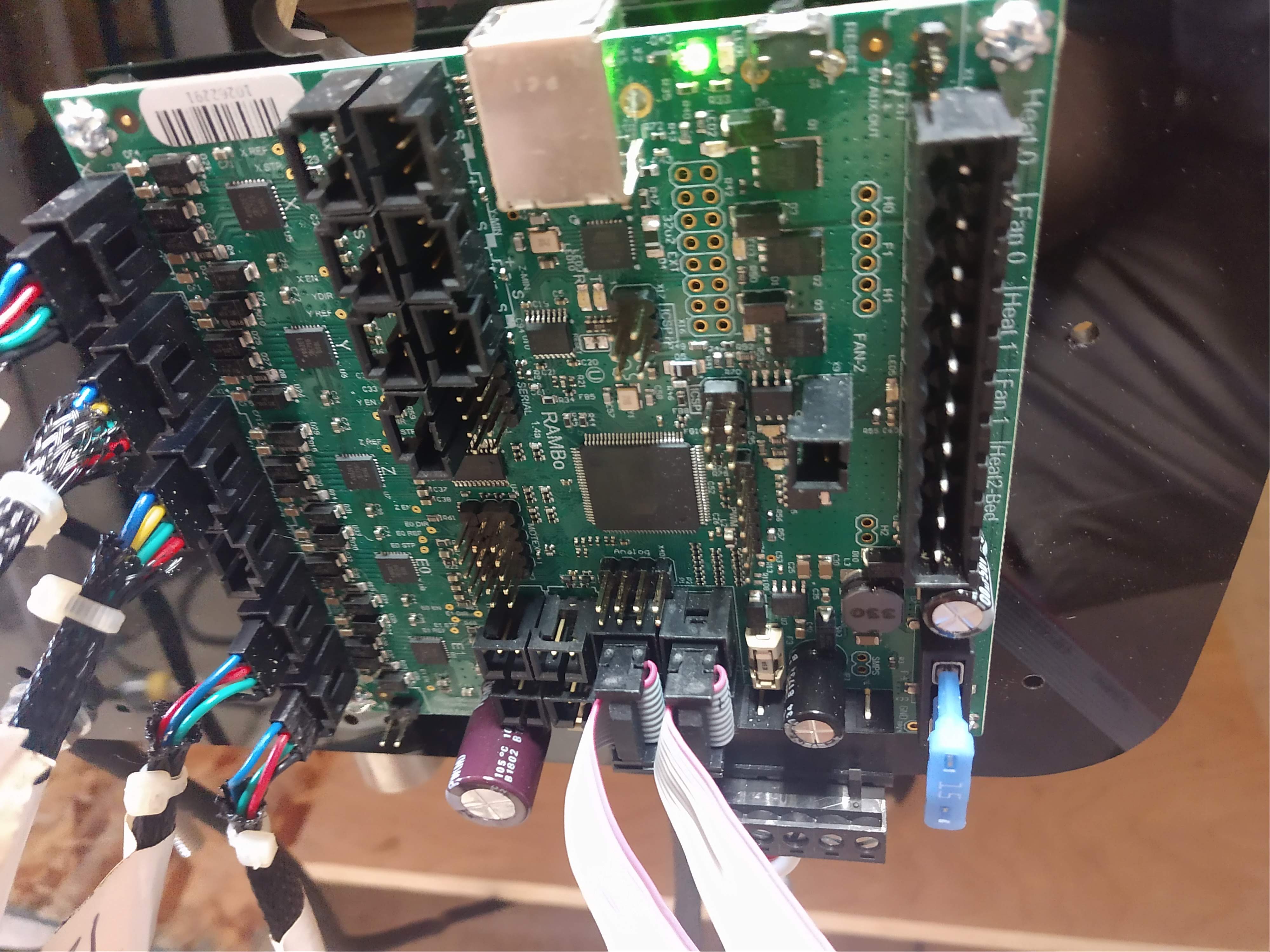
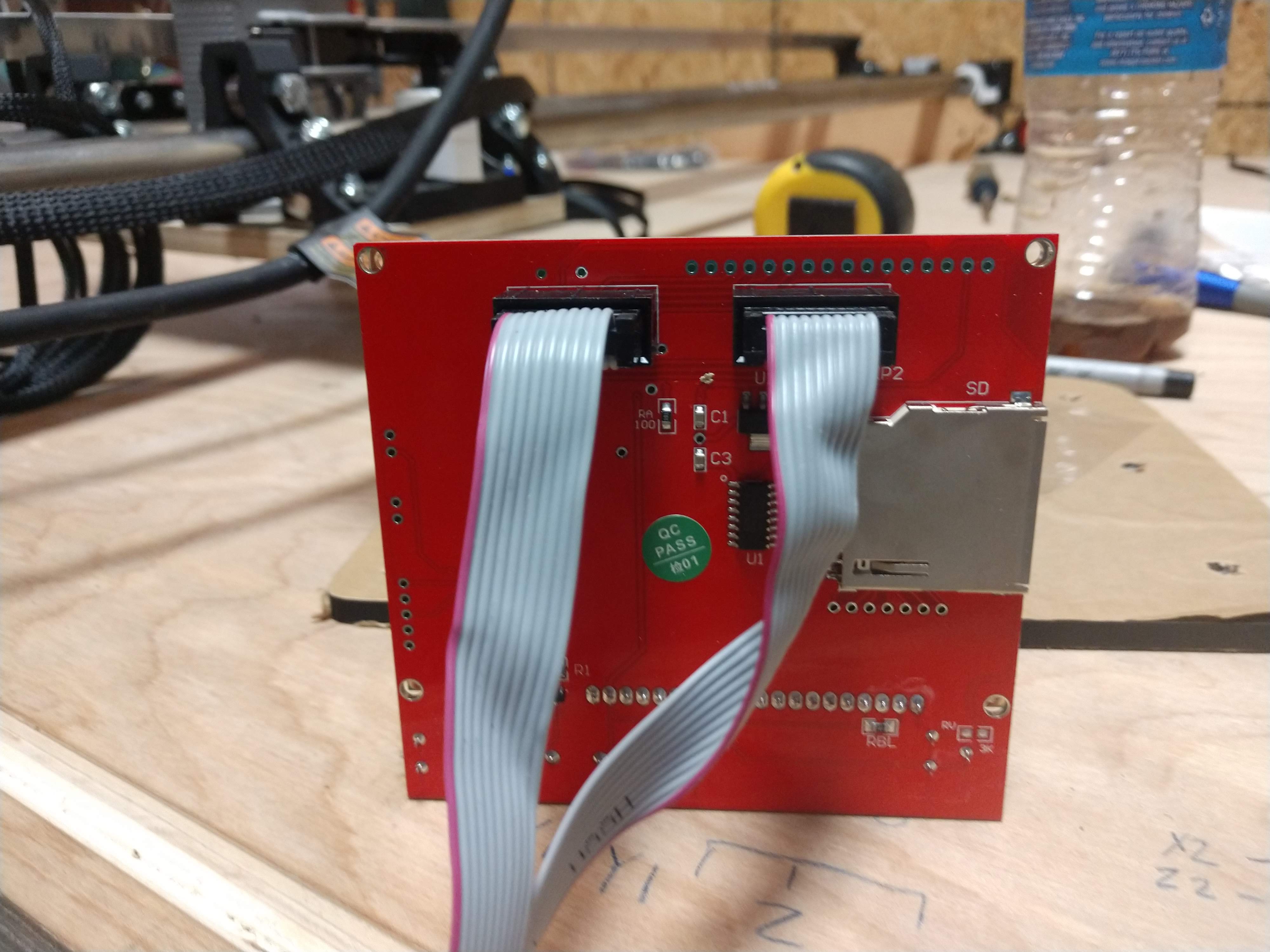
Okay, so these pictures show the configuration as of June 2020.
For the LCD, when the cable ports are oriented towards the top, and the text labels are right side up, the ribbons need to be on the left. We’ll call the left one cable 1, and the right one cable 2.
on the Rambo, if you orient the board so the large capacitor (black cylinder sticking up) is on the right side, and the cable ports are slightly above and to the left, then, again the red cables need to be facing left. The LOWER port receives cable 1, and the upper one receives cable two.
Hope this helps and clarifies what worked for me.
!
Thanks to all who posted about the LCD cables. Clipping and reversing one end of each cable resolved my issues was well.
1 Like
I’ve tried all the possible cable iterations
and get the following.
This
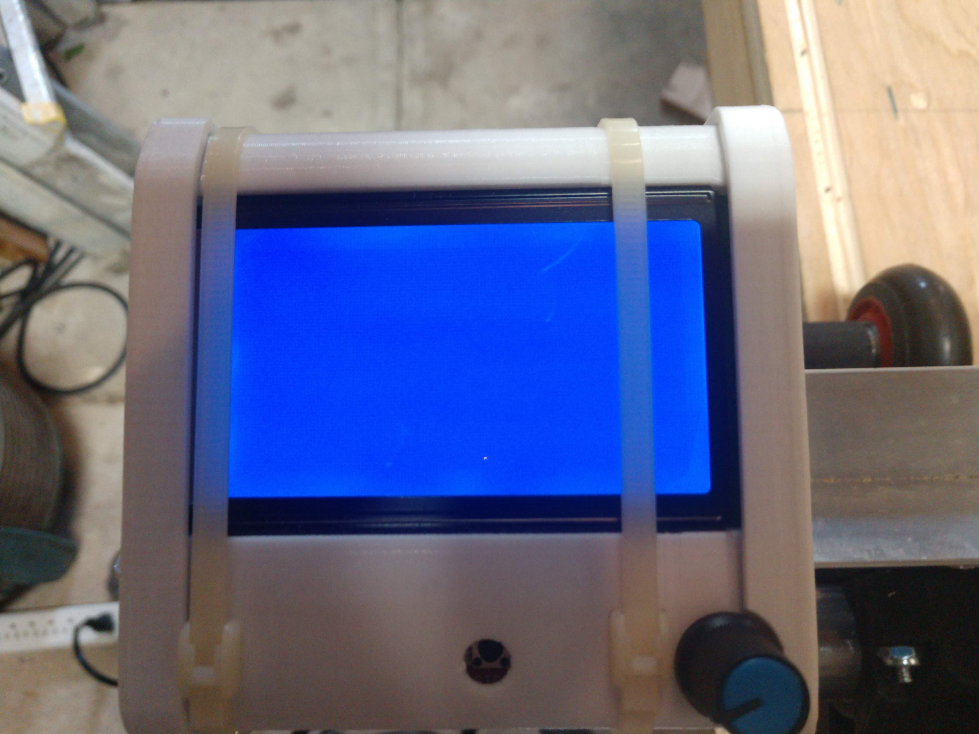
Or this
Here’s my wiring.
Rambo 1.4 with end stops from V1 in June
So what’s next😕?
Do you have EXP1 & EXP2 swapped at one end?
Fred has another thread. The problem was the rambo wasn’t flashed.
I just used exactly the same method: removed the notches of the cables so I can rotate then and have red strip on the left as per Rambo 1.4 schematics.
Once I did that, my LCD came to life 
Thanks.
1 Like
I did exactly what you showed in the pictures. Thanks for the help
1 Like
First time post, just finished assembling my lowrider. Starting wiring and had my LCD flickering and clicking. Flipping the wires like this fixed it for me, booted right up. Snippers broke half of the top part of the shroud but thats ok :>
Pictures made it very easy, thank you.
2 Likes