Ok, I was just set straight, I’m on board with how the FET works now.
Ok, I got it working. Actually really well too. I set the spindle speed to 12000 rpm and get a perfect 10V, and at 6000 rpm I get 4.88V. Close enough for me, just about linear. This is what I ended up doing:
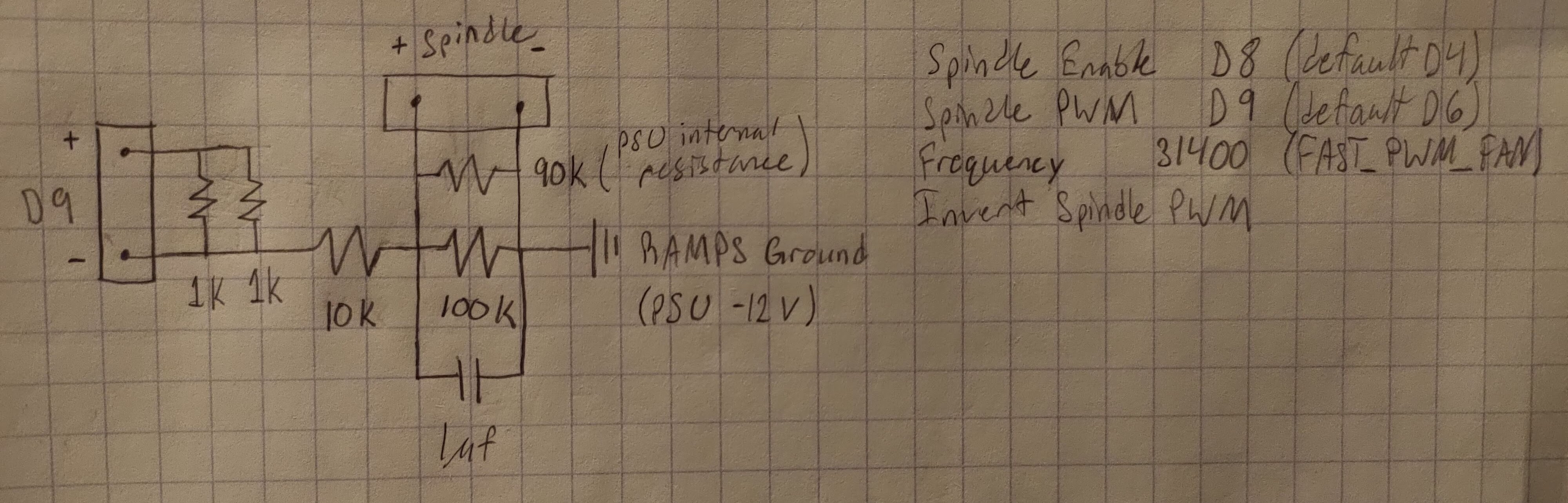
The two 1k resistors are in parallel for pull up just because it doubles the thermal mass, so each one heats up less. If someone else tries this, they’ll have to measure the internal resistance of their PSU’s 10V input and modify the voltage divider based on that.
I also set up a relay from the RAMPS to the spindle PSU’s on/off header. I’m not really sure if this is strictly necessary because just setting the spindle speed to 0 turns it off too (M3 S0), and M5 also sets the speed to 0. Maybe someone will tell me it’s actually a good thing I wired the relay. Redundancy I guess.
Do they heat up significantly? There is only 12mA going through them.
Power through the resistor is (V^2)/R, or (12^2)/500. Or if you want to first get current, I = V/R = 12/500 = 24mA, P = RI^2 = 500*0.024^2. That’s 0.288W, which is a bit much for standard quarter watt resistors.
If you only had one (and it was still 1k) though, it would be 12mA and 144mW. Not sure why you need both for a pull up, but I will trust you’re paying closer attention than me.
Initially I tried using a larger pull up resistor at 4.7k, but it was making the voltage divider not very linear. At a set 6000 rpm, I was getting more like 4.3V. I’m not too sure on why exactly this is, but I’ve been told that a lower value pull up would make it more linear, and it seems to be correct.
1 Like
I want to followup on this post after I have been having some issues… Will also follow up on the original thread you referenced.
I started having random milling errors. It would random detour… so far the way I have resolved these is to disable the spindle control. My current working theory is that spindle control is probably fine IF you are using PWM255 mode on an 8 bit RAMPS/mega256 setup but the RPM mode may be causing corruption elsewhere even thought RPM seems to be working… So for now I would hold off on the RPM fix and use PWM255 until I confirm.
Any progress on this issue?
What specifically are you asking about? There were a few things discussed in this thread. Initially I was trying to get a live RPM feed back to my controller board, but quickly abandoned that in favor of simply setting the RPM through gcode and assuming it’s close enough to reality, which works quite well.