So I know this topic has been beaten to death in a few forum posts, but rather than append existing posts with new/off topic questions, I decided to start my own.
I picked up the Neje 30w (7.5*w) module and have it hooked to my MKS Base board running Marlin.
I have done quite a bit of perusing on the forums, and found Ryan’s fix to the marlin.cpp file to get rid of the pesky 10hz delay on updating the fan speed parameter, for faster response when using M106/M107 to control the laser power.
The laser module is a 12v, with a TTL/PWM signal that can handle up to 12v, so driving it directly from D9/ fan output won’t fry it out, but due to the way ramps (or at least the MKS Base variant) works, the FETs on the fans and extruder outputs do not switch Vcc - They switch ground. So by wiring +/- for the laser to +/- on the power connector, and wiring TTL/PWM to Fan +, the laser is always on full power. If I were to wire TTL/PWM to Fan -, then the logic would be inverse - M107 would turn the laser to full, M106 S255 would turn the laser off, etc.
Is there a way in Marlin to invert the fan pwm logic, or would I be better off remapping the fan to an alternate pin?
Alternately, and I did test this, wiring laser + to power +, and wiring laser TTL and laser - to Fan +/- respectively does work, but that means I’m applying the PWM duty cycle to the main power as well as the TTL logic, if that makes sense. Not sure if that’s good for the laser module with long term use.
Would appreciate any advice. Personally I would like to stick with the fan terminals, if for no reason other than the screw terminals are more compatible with my wiring.
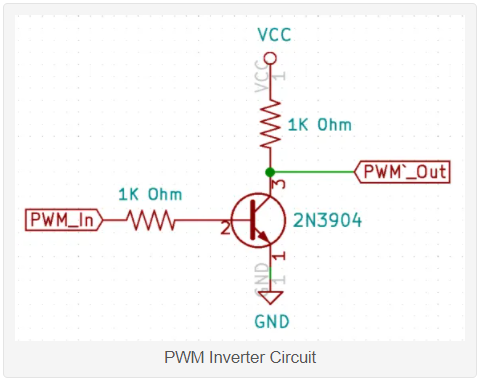
I would have thought that inverter would need some form of biasing on the PWM_in in order to work as the FET on the RAMPs is working just as a switch to ground, so when the FET is conducting PWM_In is grounded and the 2N3904 is turned off so PWM_Out signal is high, but when the FET in RAMPs is off then PWM_In is …nothing…there is no voltage there…so the 2N3904 is still not conducting and PWM_Out is still high. A 4k7 resistor from the transistor gate to Vcc would provide the biasing required to turn the transistor on whenever the ground was missing from the RAMPs FET.
have you successfully used that circuit as is Tim? Perhaps I am missing something here?
@cncwookie pulsing the supply of your NEJE will also pulse the inbuilt fan…not something it will appreciate at the very least…I don’t think I would run a laser like that. The other ‘thing’ might be the application you are using to generate your gcode will have to be configurable to use M106/M107 rather than M3/4/5 for laser intensity.
Yes, I had it connected to a RAMPS stack and my Neje laser for testing. I was able to vary the laser output. I don’t know that much about the finer points of electronics, but it did function as advertised.
I’m assuming you are planning on using the fan pin and then fan g-codes to turn the laser on and off. Based on other forum posts, you will get better results by enabling the laser support in Marlin. Ryan/Jeff has enabled and tested Marlin laser support for a few boards. Ramps is not one of them, but here is a listing of the laser differences between the configuration_Adv.h files of the Ramps board and the Rambo board, which has laser support enabled.
So you will be using pin 2 by default. This will almost certainly be a 5V pin and won’t have the issues of the fan pin.
I did not find a pinout image for the 1.6 version. Here is a link to the 1.4 pinout. The D2 pin is in the AUX 1 block. I’m not sure what the asterisks next to the pin means.
As for driving the laser, at least one person on the forum struggled with using the M3/M4/M5 g-codes, but everyone has had success using the inline commands where the laser power is specified using the ‘S’ parameter to G0 and G1 commands. You will find a test file created by Ryan in the first post of this topic.
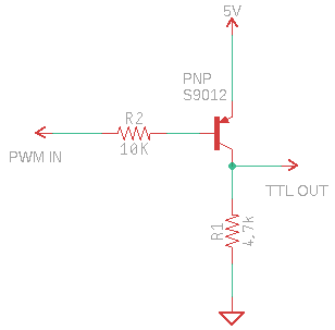
Thanks for the confirmation Tim… I don’t really see how it works as described. I did find another example of a single transistor inverter but using a PNP transistor and that makes a bit more sense to me but if it does work it is obviously something I mis-understand so I will shut up!
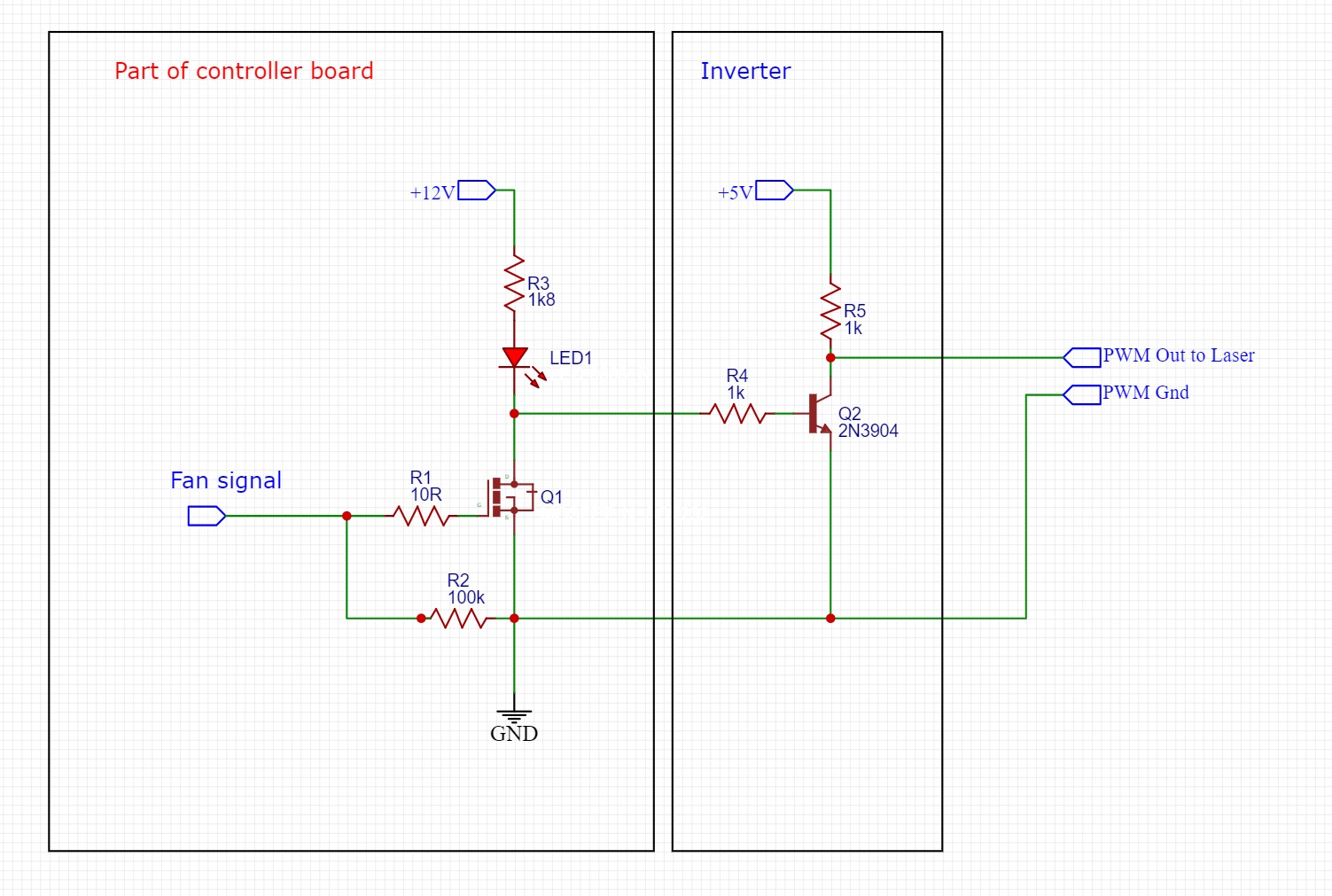
PWM _In goes to FAN -ve, ground to RAMPS/Mega2560 ground , 5v to Mega2560 5v and TTL_Out to laser PWM_In
Having thought about the whole picture I guess the inverters transistor is driven on by ‘leakage’ through the Fan LED on the Ramps board when the FET is switched off thus grounding the PWM output. When the FET switches on the transistor is forced off as its base is grounded thus allowing the PWM to rise to 5v
This is a bit sloppy as if the LED fails the circuit will stop working too, I would have placed a 10K biasing resistor between the left side of R4 to +5V to bias it on unless the FET is conducting and actively switching the transistor off.
It also raises the transistors gate voltage above it’s rail voltage… something I thought was not advised.
Thanks for all the advice and suggestions - Upon further reading I did decide to make sure I had the latest firmware, and went with the M3/M4/M5 (and linear motion for G0 Sxxx moves).
I chose a slightly different approach, and so far testing seems to indicate it’s working just fine. Unfortunately, the MKS Base 1.6 has a lack of available extra pins, especially hardware PWM pins that the docs call for for laser PWM control, so I opted to use the two extruder FETs to control the laser. I have laser power wired to E0 +/-, and SPINDLE_LASER_ENABLE set to that pin (10), and changed SPINDLE_LASER_ACTIVE_STATE to HIGH. I have the laser PWM pin wired to E1 - pin, and set SPINDLE_LASER_PWM_INVERT to true. This solves both the issue of inverted signaling when switching the negative pin on the FET, and also stops the laser from powering up when the board is first powered / rebooted.
It’s not the way most people would do it (wiring laser power to board power supply and finding a spare 5v PWM pin), but it works for my application - since this machine is specifically a CNC router or laser, I don’t need the extruder heater outputs for an actual extruder - and most heater cartridges for 3d printers are either 30 or 40w, (and the NEJE laser module is 30w input), I’m within spec of the current rating on the FET.
Now that I got this bit sorted, I need to figure out a ventilation solution before I go cutting and engraving willy nilly and smoke out my basement. =]
So i did a few test burns over the weekend… Still trying to dial in speeds/power for etching. But i noticed a lot of stuttering in movement. I can try and post a video if it’ll help clarify. I’m almost wondering if upgrading to a 32bit board would help improve performance. I know the mks base (ramps basically) is an 8 bit board, and I’ve read that floating point calculations especially with arcs can be trying on the 8 bit processor.
Can anyone with more experience offer some insight? Would it be worth upgrading to the skr pro board? Or am i just missing something in the firmware settings for marlin laser support?
When i get home from work ill add more info re firmware settings etc.
Not sure if it’s a rigidity issue - I’ve done routing jobs with the dewalt 660 before I put the laser on, and those came out just fine.
I’ll try and get a video later if I can, but in addition to rough movement, the laser itself kept stopping and starting. (for all I know, the 6A power supply from V1 isn’t enough to power both the CNC and the laser module; I have a whopper 67A supply I could try - overkill, but no such thing as too much power supply capacity).
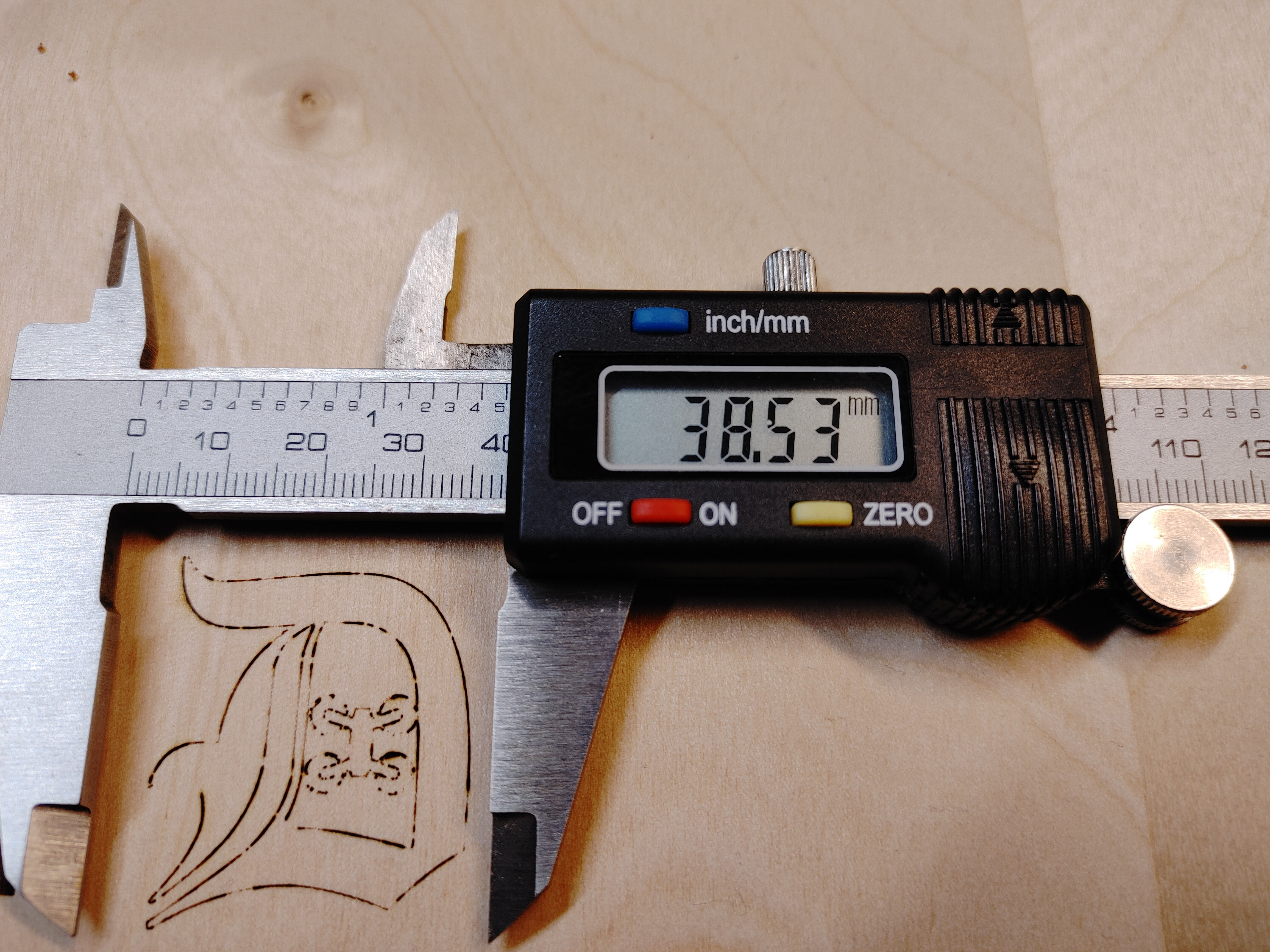
For reference, here’s the DXF I was trying to burn, and a picture of what actually came out.
The laser adds another layer of computation to use laser mode. Ryan has a post somewhere where he was testing it and the skr did go faster without stuttering.
No worries - I’m going to try a beefier power supply and see if it helps. Thinking about it - raster worked ok, but vector presented the issue… When the laser is on, its only moving on one axis. With vector, the laser is on during simultaneous X/Y movement, especially with arcs, so the added axis movement could be the straw that broke the power supply’s back so to speak. Assuming 1a on the steppers and 40w on the laser, that’s closer to 7.3a give or take.
I’ll report back when i try the bigger supply - if its still giving me issues ill definitely consider an skr pro.

