I don’t have a laser, but I’ve helped a couple of people get their laser working. First, there is a potentially “easy” way of getting it working. You can plug TTL/PWM input into a set of fan pins and control the laser with the g-codes that set fan PWM for those pins. Depending on how these pins are wired, there can be issues. And even if they work, I’ve read complaints about poor performance in Lightburn (popular laser driving software) when driving the laser this way.
Fairly recently there has been laser work done in Marlin, plus Ryan/Jeff have enabled and tested the laser support for some boards. They are only enabling the laser support by default on boards they have personally tested, and the Ramps boards in not one of them. So your first task will be to make a few changes to the firmware and flash the board. Here is a list of line differences in configuration_Adv.h between the Ramps board, which does not have the laser enabled, and the Rambo board, which does.
The pin to use for the laser is defined in Ramps.h in these lines:
//
// M3/M4/M5 - Spindle/Laser Control
//
#if HAS_CUTTER && !defined(SPINDLE_LASER_ENA_PIN)
  #if !NUM_SERVOS                                 // Use servo connector if possible
    #define SPINDLE_LASER_ENA_PIN              4  // Pullup or pulldown!
    #define SPINDLE_LASER_PWM_PIN              6  // Hardware PWM
    #define SPINDLE_DIR_PIN                    5
So your laser will need to connect to pin 6 on your Ramps board. You can find a schematic for the Ramps 1.4 board here. Pin 6 is on the Servos block and there are ground pins for the other wire in this block also.
You can test your laser using the M3 and M5 g-code commands. With this laser code enabled, Marlin will also allow you to drive your laser using the G0 and G1 commands with the S parameter.
Robertbu mentioned this thread to me, so here is what happened to me recently
there are pins that can be enabled on ramps , essentially any of the pins on the lower part of the board, all the way to the bottom right bank, servos, laser/spindle, others down there. you can also find a single 2 pin for another fan (very small), as well as the large D9 D10 D11 terminals on the left that require a secondary power source , any of these pins can be modified to be enabled in various degrees (on,pwm,??) based on the skill of the individual. I could not get my servo pin to disable after enabling for torch on. so I had to switch to D9 I believe. this required the least rewriting and thus chance of error compiling. you need to select a mode in the config, the first config page near the very top, to choose FEE fan extruder extruder FFE fan fan extruder or SF spindle fan. each mode changes the code assigning gcode control over pins. in SF which I used, the first D pin became usable via M105 (ON) M107 (OFF) succesfully. you can check the file called (ramps.marlin) deep in the files, right click open with text editor, to see or change pinout utility for marlin that correspond to the compilers editable choices.
personally I’m trash at c++ so the least amount of editing really worked in the end. I learned that “M105” has to be capitalized. the D9 spindle pins operate in a speed control mode that can be utilized via “M106 (speed, i,e, 3200)” “M106 3200” via gcode control. in estlcam you can have it add control codes automatically for each move I never use 106 because I needed a solid on off trigger.
well I think that just about covers it. let me know how it’s going, hope to see something soon!
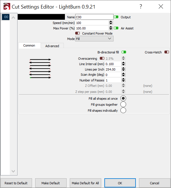
Got it to work connected to D9 pins, but when I use Lightburb and using the ”Fill” burn it seems to overburn abit each pass, it goes outside of the shapr it should burn.
I seen similar issues on the forum, but I cannot remember the solution and search is not turning them up. Is there a kerf setting in Lightburn? Could this be a focus issue with the laser so that it is burning beyond what Lightburn thinks it should? Are you using inline commands rather than M3-M5?
My “solution” for this issue was setting up the control board with GRBL instead of Marlin. At least at the time I was fighting through it, Marlin support for a laser was a hack, whereas it was more planned and mature with GRBL.
You may need to disable or zero the “Overscanning” switch/value, to prevent the fill scan from going past the outer edge, although I think this is just a 2.5% beam-width overlap between the “fill” scan lines and the outer “line” burn, if you are using one. Also you have to do some math to figure out how many lines-per-inch based on your laser’s beam width at the top of the material. Then set the “Line interval” if you want spacing between each scan-line.
I will try the ”kerf” setting to a negative value, I’ve tested to turn of overscan, but didn’t get the results I was hoping for.
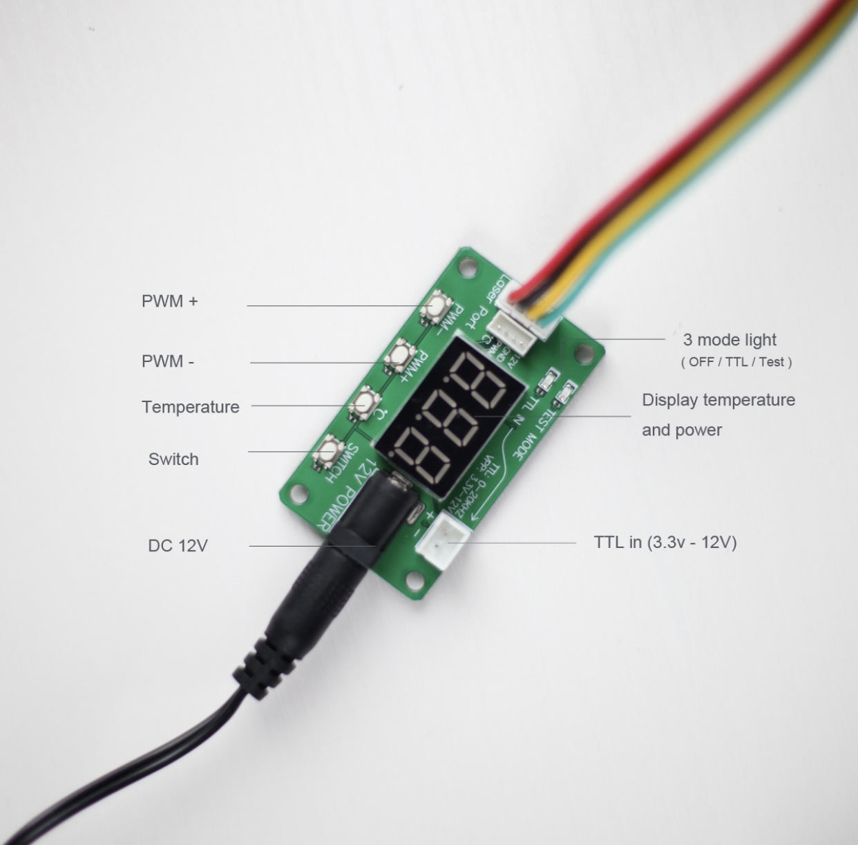
Also right now I have connected the laser to the little module. From the module I’ve added a 2 wire cable to the TTL connector on the board. It works but I have thought about it?
Or should I skip the module and connect the 12V, GND, PWM directly to the ramps to get a better smoothness of on/off pwm? Or am I wrong here ?
I believe the kerf setting is only available when using the line function.
I’ve used it both ways and noticed no difference. I currently have it wired direct on my rig, but when I had it running through the test board, it was nice to just manually turn the laser on at .001% for positioning. Lightburn only goes down to .01%, which is still quite bright without safety glasses, at least with the 7w unit. But I kept forgetting to set it back to pwm mode before starting a job.

 I never use 106 because I needed a solid on off trigger.
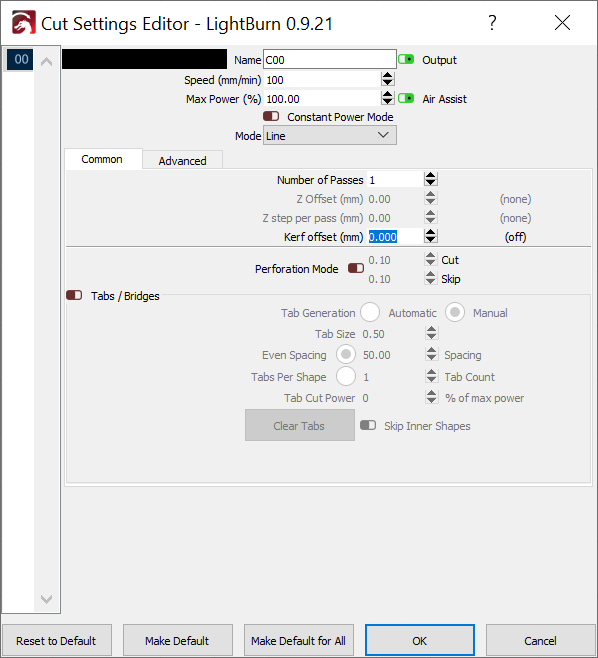