So I’ve been working on a redesign of my LowRider v2, and I’m cutting out the z-gantry portion and just tacking on a linear motion z-axis that rides on the x-axis. While reconfiguring the y-axis, I’m looking at this from the front of the machine and wondering if I could move the y-motors to under the rail, basically flipping the side the y-motor mount goes on the plate (with some modification to the mount of course), swapping the rail for a 20x20 v-rail and just put the belt in the rail. That way I can also use Derlin wheels to secure the side to side motion and act as a belt pulley. Anyone see what I am seeing in this or do I need to spend more time visualizing the design? (also swap the skate wheels for Derlin wheels too) Who knows, maybe I’m just redesigning the Lowrider to look more like a traditional CNC machine and getting lost in rabbit holes.
Looks like a big ol’ can o’ worms to me.
By changing the Z axis to the gantry, you are going to need to sacrifice some rigidity by moving the X axis further off of the drive plane. That is to say that no matter how thin the sheet material you’re cutting, the X axis must be acting at the highest level that the Z axis can accommodate. The LR2 design as-is allows the XY plane to sit at the lowest possible Z height for the material that you are cutting at pretty much all times, which reduces the moment arm on the bit and increases the effective rigidity. This is one of the things that allow the LR2 X axis to be significantly larger than the Primo’s even when dealing with the same structural material. (1" DOM or stainless tube.) It’s by no means the only thing, the Primo is largely dependent on the single gantry tube as opposed to the LR2’s dual rails.
One of the largest defining things about the LR design is the Y plates being the mount for the Z axis. Subbing out the skate wheels for delrin wheels, and adding a constraint for the Y drive in the X axis… Honestly, I would see a linear rail as a superior version of that, hands down every time, and once you’re installing a liner rail, you really are going to a more “traditional” CNC machine design, and are probably better off starting from a design that works that way in the first place.
The extrusion based X axis gantry with the Z axis mounted to it and moving all end up having that asymmetrical “hunched” look in order to keep the centre of mass between the Y supports, whether those are wheels (Or skate bearings on tube) or linear rail bearings. The spindle/router/plasma cutter is going to put some torque on those mounts, so the better centered it is, the less effect that torque will have on the accuracy of the machine. The LR2 design doesn’t really lend itself well to that, and the pictures of conversions that I’ve seen done that way end up looking funny to people more used to the way that other machines end up looking. I think it’s a testament to the LR2 design that they continue to work reasonably well despite having known and apparent flaws like that.
Disclaimer: I have my worries about it too. I’m building an LR2 myself, and have sort of “contingency” plans to do something if I end up with tracking problems, but if I start wanting to do a major redesign, I’ll likely just start over with a different base plan.
I’ve looked around at various designs, and there are some that will give results that are on par with professional machines in terms of speed and accuracy. Some of them are even quite reasonably priced.
I suppose that what it boils down to is this:
What problems are you trying to solve with a redesign?
Would those problems be better solved by starting from something entirely different to begin with?
2 Likes
The biggest problem I have is z-axis skipping steps when lifting, I don’t have issues plunging like most people. I have done everything I have found on this site to mitigate it but it still crops up! Sometime right away in a cut or 45min+ into a cut. I’ve tried reducing z rates, adding ramps in plunges, increasing z motor current (up to 1200mA!) and it seems more apt to happen when the spindle mount plate is to one side or the other of the x-axis(causing one side of the x-rail to be higher than the other). I’ve even gone as far as using solid couplers on the z-axis screws. This last one did help tremendously with added lube to the z-screw and z-rails, but I would still get a z-axis skip well into a 3-hour cut. When that happened, I stopped using my LR2 and have started this redesign.
This is a valid and legitimate concern, but are you sure that going to a single Z motor is going to fix it?
I’m going to treat this as a problem solving exercise…
If you aren’t having problems plunging, then it’s unlikely that ramping the plunge cuts is going to help any. Skipping steps upwards usually means that the motor is having difficulty with the lift. Reducing acceleration is probably more to the point than target feed rate, but with the current bumped up to 1200 (This is actually where I have my Primo set for all axes, BTW) even the default rates should be possible.
Moving to a single motor on a moving gantry is also unlikely to solve the problem.
So you need to reduce the load on the motor, or get stronger motors.
Stronger motors are unlikely to be the problem if you’re using the 76 Oz-in motors provided by the V1 store. I have 84 Oz-in motors myself, but since it’s really current that limits power, they aren’t really going to be any stronger.
So how to reduce load.
Let’s start from the cheaper solutions I can think of.
-
Reduce friction. Seems like you’ve already looked at this already, but I’m including it as a part of the troubleshooting exercise that I’m treating this as. Check for binding in the Z axis, particularly when lifting. This can also sometimes present itself in slightly rough movement while lowering, if there is some resistance to moving, it might stutter slightly while lowering.
-
Reduce the lead of the Z screws. The normal screws that come with the V1 kit, and are most common are 4 start, 2mm pitch screws, with a lead of 8mm/rev. Similar 8mm screws are available in 2 or even 1` start, which reduces the lead to 4mm or 2mm. This will result in effectively doubling or even quadrupling the effective lifting power of your motors. (This also has been shown to help prevent the Z from dropping after you turn the motors off.) The cost for this is minimal, though the 4mm and 2mm lead parts are less common, and somewhat harder to find. I’ve actually been giving serious consideration to using 8mm threaded rod (1.25mm pitch/lead) for mine, since I have it. This would require an adapter for the nut, but that’s actually a fairly simple matter. I doubt that the speed would be a problem. (I plan on building according to plan before trying any modifications.) Anyway, lead screws with a shorter lead to them should cost quite little, and can have a dramatic effect on applied power
-
Try a higher voltage/power PSU. If the problem is a “brown-out” of power, where your PSU is not able to supply the voltage needed to get to the target amperage, higher voltage at the PSU might help. Stepper motors generate back voltage the faster they move, This voltage works against y our power supply. Going to a 24V power supply gives the stepper driver far more room to play with, ensuring that it’s going to be able to apply full current to the stepper motor at higher speeds. This us usually not necessary with any V1 CNC machine It might be a sign of a weak PSU as well. This does sometimes happen, and a higher rated 12V PSU might be able to solve the problem as well. Generally, most boards except possibly an actual Mega2560/RAMPS1.4 can take at least 24V power input easily, and a 100W (or so) PSU will cost about the same in 12V or 24V. with 24V, you might have to replace things like fans, LED lighting, etc. though, so the cost for this is potentially higher.
In your case, I would at least try the cheaper solution of different lead screws before going to a full-on redesign. I would have very high confidence in that resolving the problem.
Out of curiosity, did you keep your brass screws loose on your lead screw? Also what’s the amperage of your power supply?
2 Likes
I purchased the kit from the V1 store, so the power supply should be plenty. They are 4-start, 2mm pitch / 8mm screws. The brass screws that hold the leadscrew nut in place were tightened then backed off half a turn.
I have however believe it to be the firmware possibly? I am running a SKR 1.4 Turbo and built my own firmware enabling stealthchop and hybrid_threshold for quieter operation. I believe this could be the issue. I built a version with those disabled (cleared eeprom data) and they some noisy motors and even sound like they’re putting out more power. In conjunction of lowering my Z rates, I haven’t had any issues yet on the past two cuts I’ve made. I can seem to speed up x/y movement tremendously without any issues. Im going to do a 3rd cut soon with Z movements back to default.
current rates: (this is too slow for me to be happy with)
20mm/s feed rate
2mm/s plunge rate
what I was using:
60mm/s feed rate
20mm/s plunge rate (apparently is way too fast)
What I have managed successfully with the new firmware (what I want ideally milling wood):
60mm/s feed rate (DOC 1/2d of bit per pass with 60mm ramp) (takes 1 seconds to get to DOC)
8mm/s plunge rate (I want to really get this up to 15mm/s) (8mm/s I started seeing my failures on the old firmware)
Wow that 60mm/s and 20mm/s vertical is very fast and explains some of the issues you were seeing. Im sure the acceleration to that speed was extreme which caused your issues.
Out of curiosity, why do you want to plunge z so quickly? I can see the x/y speed if you’re running production parts but z wouldn’t be so significant for your overall time would it?
2 Likes
Mostly inexperience working with the lowrider. I didn’t realize Z-axis was so fragile! The last CNC milling machine I helped build, could tear through those speeds and not miss a beat! I mill a lot of hole patterns for jigs from everything to manufacturing assemblies as temporary place holders (circuit boards for testing to as large as some mechanical assemblies that need aligning) to jigs for crafts with yarn and rubber bands. I also do sign work for some of the local parks and rec centers(for free, their budgets aren’t the best), so a lot of pocketing happens too.
It isn’t fragile it is just designed for slower more powerful movements.

When you build a machine like this you need to choose your gear ratios. power vs. speed. Some guys (Dan) is running his Z axis at 45mm/s for leather cutting.
When trying to run at 60mm/s on a super low gear ratio you lose all your power at about 35mm/s. I geared it for full power at 15mm/s and then stepper power tapers off very fast at RPM above that.
Most Z plunging is done between 1-10mm/s, the only reason I even set it for 15mm/s is for Z rapids.
I can’t really imagine what you would be cutting to where you want a 20mm/s plunge.
Here is a 22mm/s plunge and it is really pushing it on a 14" usable axis…not a 60" like a LR.

4 Likes
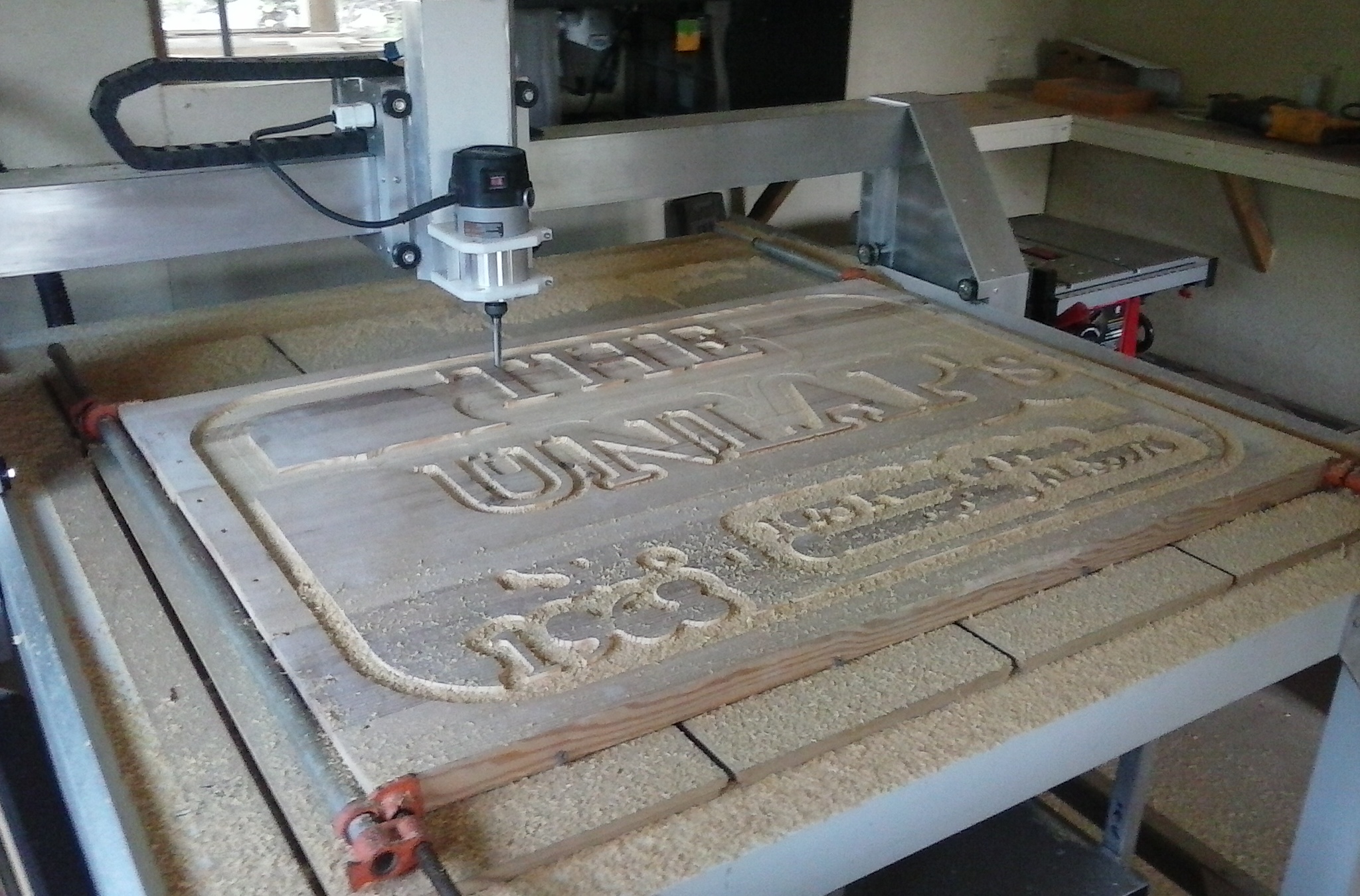
Update. Well I built it anyway. It’s now more what I expect. It’s likely this cheaper spindle that was causing me problems. You can hear it in the video below bogging down.
For a 40-year-old worn-out v-bit, I had worse outcomes with a brand new v-bit on the original design.


2 Likes
What speeds are you running? Looks a lot slower than what I can carve on the standard lowrider.
Did you buy your z axis as a kit?
20mm/s feed
5mm/s z plunge
These were numbers left over from when I was running the LowRider2 from my previous build that was failing not even 5 minutes into a cut (z-skips in raise moves). Also, it’s a V-Carve run with an ancient v-bit. I forgot to set the pass shallower for this older bit.
The z-gantry was bought as a kit from openbuilds; probably the most expensive part of the rebuild.
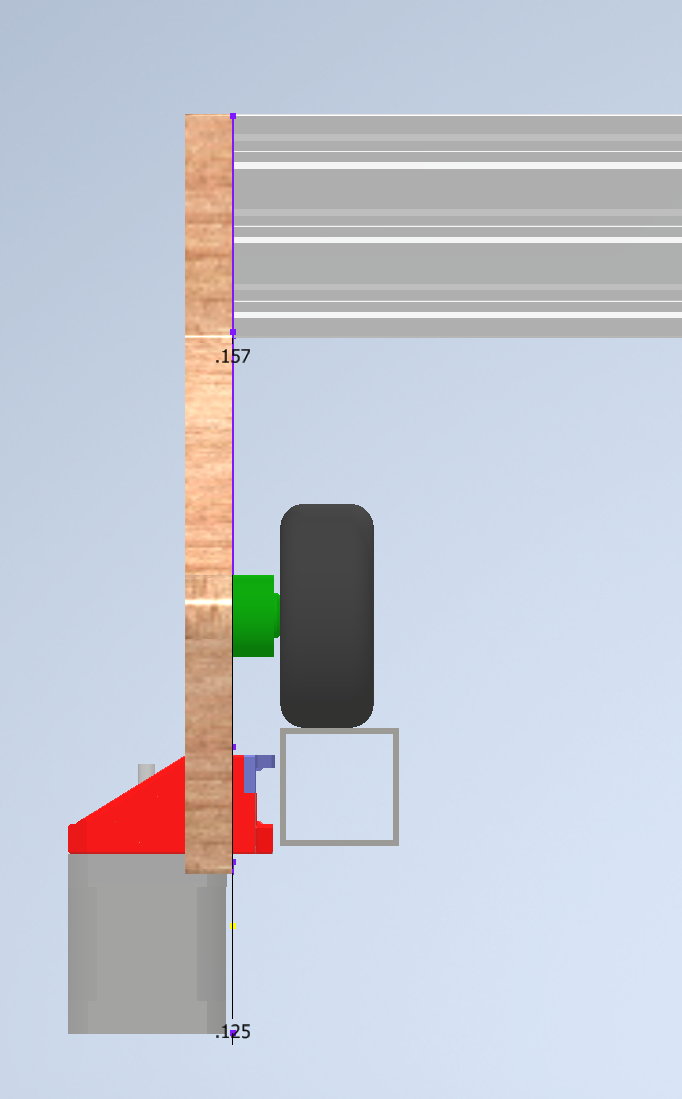
I also plan on shortening the gap between the spindle and the z plate. I goofed on the design of the clamp and added the 15mm ring to the spacing from the plate to the spindle. It should be 20mm, not 35mm. (The thickness of the ring of the clamp is 15mm)
Nice! Will be interesting to see how fast you go. I am typically cutting at 22mm/sec with a 1/4 in but with a 6mm doc on the standard lowrider.
How do you like the z-axis? Is it decent quality? I have been looking at their stuff but wasn’t sure if it’s well built.
It seems to be stout. Time will tell how well it holds up. I used to do DOC=1/2 bit diameter at 30-50mm/s on an old machine I used to operate for wood and plastics. It was a 4ft x 4ft bed, all aluminum frame with rack and pinion for the y-axis. Much more stout than this design. It ripped through material like butter!
Sounds like a nice machine! Also sounds much more expensive
I’m no expert but couldn’t the worn out v bit also cause the spindle to bog down like that too? Harder time cutting = more resistance?
So… I haven’t been around in a while and recently got to look at the CNC machine I used to work with in a shop a while back that was as stout as they come for milling hardwood. It broke, so the owner called me to take a look at it. Now that I have a better understanding of why it was such a stout machine, after looking into it… and rebuilding it from basically scratch because all the electronics were covered in dust, It seems that all its motors used a closed-loop system for its motors. (this is why it could cut 1/4in passes without a hiccup or a missed step) The topic of this thread started because I was having issues with the z-axis becoming unaligned from missing a step while lowering into the cut material and I ended up fixing the y/z axis and moved the z-axis to just 1 location on the x-gantry. However if I were to revisit this, I would have tried some closed-loop stepper drivers. Has anyone else tried close-loop stepper drivers on their motors like the BIGTREETECH S42B featured in this video?

Those were mentioned a while ago (around the time of the video coming out). I expressed some concerns (mainly, that you are trading in accuracy of the open loop step for the accuracy of the closed loop sensor, which is worse until you get to the point of skipping steps). There were a few people that tried them. But, unfortunately, most of the complaints were around the difficulty setting them up, and the flakey firmware versions.
2 Likes
The TMC drivers are also a bit more “smart” than previous drivers. They turn the current up and down more so than the old drivers. So they idler lower “cooler” and can turn up if a higher load is sensed. Closed loop would be a bit better but skipped steps should not really be an issue.
In my experience, I can push the machine far beyond needed tolerances before I come close to skipping steps.
Smart CAM and proper tools can get you just as far as brute force and poor CAM. Have a look at my drag race videos to get an example of this. Some people have issue with the recommended starter settings (Tom S’s build video is a great example), while I ended up easily pushing my machine 32X faster than recommend starter values.
1 Like