I am sure the question has been asked before but i couldn’t find it searching the forum.
Why are the X and Y steppers on the rails that move? It works but it makes cable management a lot harder to get right. If the Steppers were moved to the Left and Back corner mounts then the cable management would be easier.
Pros to the change:
Easy cable management (No moving wires for X and Y steppers.)
Less weight for the motors to move have to move around.
Less Hardware required. A stepper and a single idler bearing per side instead of the current two idler bearing setup.
Fewer parts to print. (possibly )
Cons to the change:
Would require twice the timing belt length. (but it won't stretch so there isn't an accuracy problem.)
Would require more specific designed parts instead of printing multiple copies of the same corner pieces.
I am a software developer not an engineer so they be some other reason I don't know about. But I love to tinker. I am still building my first MPCNC. Almost done. I love the design and I am extremely impressed with it. Hats off to Ryan and all the work put into this. When you introduce someone new they can't help but to have a fresh opinion. I am already thinking through possible 2.0 design changes I would like to try if I get the chance. Please feel free to tell me if any of these are bad ideas so I don't waste time in the future.
Move the X and Y Steppers to the corners.
Redesign the Corners so the legs stick up through the assembly as high as I want.
So the Z axis can be customized higher or lower for project need. Most of the time will will keep my Assembly low so i only have about 1.5 inches of clearance. But on occasion I may want to work on something that is 6 to 8 inches thick. I know you will say Drop table. But why custom build a table to match my changing height needs if it were easier to just loosen the corners and slide them up the conduit?
Also I may want to mount a plexy glass shield to those legs if they stuck up a foot above the corners.
I also considered an idea that would raise and lower the corners with a hand powered mechanical assembly. Something as simple as a bolt sticking through the conduit and a plastic sleeve with threads that goes up or down as it is twisted around the conduit. (This probably won't work with plastic i'll admit)
Make the Corners about an inch longer on the sleeves so they hold the conduit a little more square.
Make some sort of an EASY notch for a tape measure to hold onto the corner pieces to help measuring the squareness of the build. That was a very difficult task with a lot of guesswork because the tape measure had nothing to hold onto.
Find some way to make the moving X and Y parts stay more square when the steppers are disabled. aka when moving the Gantry by hand.
Maybe make the conduit sleeves hold more of the conduit by a couple inches. Even if that extends an inch or so outside of the machine it could help hold them more square.
Maybe have a second optional arm/conduit for each X and Y. That might be overkill but it should work.
I looked over the Auto Squaring option. I may eventually implement that. I am torn between that or eventually making so this machine can be switched back and forth from a CNC to a 3D printer. In that case I would need the other motor drivers for extruders.
I may just end up buying the Prusa MK3 and leave this machine as a full time CNC.
I can’t go over that all but the biggest downside to moving the steppers is a larger footprint. I don’t see the same downsides as you do but I think this is the least expensive smallest way to build it currently. As for the rest try it out, each person has there own uses case and that means different needs. I would love for you to try them out and share with us. I have been wrong many times so my opinion is far from gospel in this stuff. I just like to make things.
I am beyond ecstatic with it as it is, milling steel was beyond my wildest dreams and it turned out to be pretty easy. Of course I think some things can be better or change what what can’t use a little tweak?? I truly think experience with the machine can solve most of the “cons” you are listing. There is sooooo much to learn, CAM, material selection, and tool selection takes a lifetime to master. Watch the Hass drill selection video if you want to overload your brain and drilling is the easiest thing we can do.
First to Ryan. As I mentioned before I am extremely impressed with the design and how sturdy it seems. I know you must have spent hundreds of design hours to get it to this incredible state. I see why it has won awards. Yes the fact that it can mill steel is crazy awesome. I chose to build this design for a few projects I want to build with aluminum. I don’t think you did but please don’t take my words as mean or rude criticism. I just wanted to share my fresh opinion ideas and discuss if they had merit or not. You mentioned a lifetime of learning how to mill. I am starting to figure that out. I have looking for some more beginner guides on how to mill. Some information about this machine would be helpful. I have read the Getting started guides on this website and I feel I can do the exercises provided when I have a few minutes with the machine. But I have other questions like when should I plan for a tool change on a job and how does that work? I don’t think the machine can move the Z into negative numbers after it homes so how can I get it high enough to change the tool? Anyway i’ll figure it out.
Barry & Ryan,
Thanks again for feedback.
Moving the steppers: True it would make the machine have a bigger footprint. Good point.
More custom parts is more cost. Also True. Fascinating that the idea was to replace printed parts with Injection molded ones. Have you seen the $3,000 desktop injection molder? really cool tool. I am trying to talk my work into buying one.
I may attempt to prototype some of these ideas in the future after I use this design for a while. If so I will attempt to make it with several duplicate pieces.
Legs that stick up from the corners
It will get wobbly. Sigh. Also true.
I love your suggestion for the grooves in the table for the Plexiglas. I didn't build this table with enough extra space so I will keep that in mind for the future.
Have to move them all at the same time or they would crack. Also true.
Moveable arms get out of square when moved by hand. Ryans says it shouldn't be a problem as I get to use the machine and I will trust him on that. But I assume I want to make sure those are square when I home X and Y because after that the steppers are locked. Any tricks of the trade there?
If I do implement the Endstop X and Y auto squaring how do you guys accurately measure where the starting point of your material should be? I am asking because I don't know what kind of offset I would use for the origin point in ESTLCAM.
I really do want a MK3. Looks like an amazing printer for a cheap price.
So out of all of this the one idea I suggested that doesn't have problems is the idea of a notch on top of the corners for the tape measure to help with squaring the build. Yay! I had a good one!
Thank you both. I am grateful for the feedback and for the help. I am excited for the design and can’t wait to put it to use. I have my Gcode for the crown test ready to go. I will pick up some foam soon then I will start work on a long list of decorative appliques and other stuff my wife wants to spend $15 each for. (She wants 15 of them) Making those alone will cover my cost for the cost of the MPCNC. I scrapped an old Migbot (Prusa MK2 Knockoff) 3D printer for most of my parts.
After I get a few of these projects done I will likely try to design my own corners. I will post the results good or bad.
No way, not at all. That is why I was trying to be careful with my reply. It is hard to “argue” my design decisions without coming off kinda rude. So now I tend not to. I love people sharing ideas and trying new things. Face to face design meetings are much easier than over text since it usually involves drawings and hand gestures. Some obvious aha moments and the like. Please try out some of your ideas, seriously.
As a noob to this build and setup, I agree 100% plus a little more that a measuring notch would be really helpful. Accurate measurements were very tough for me to get confidently.
You can’t have a flat spot as the angle changes for every size build. The only other way would be two round protrusions from the top of the corners, but then they would be there forever and you only need them once.
It was difficult for me to measure because mine is a little bigger than the one in the picture. Work area of 14 inch by 36 inch so the outer dimensions are 25 inches by 46 inches. I am guessing roughly 50 inches on the diagonal with the tape extended that far I couldn’t push with pressure to hold it in place because it kept folding. So I was trying to hook it to one of the screws and it kept falling off. I needed another person to help hold the tape on side but that wasn’t an option at the time. If I was going to do it again solo I might use electrical tape or something to hold it in place.
Hey, my 2 cents on the legs sticking through the corner blocks, why not go the other way?
For my build I drilled 30mm holes below all the feet so that the legs can go through the table.
That way you don’t lose any rigidity and can lift the entire machine if you need a bit more clearance (with the tradeoff of it being a bit more wobbly…), best of both worlds!
Sorry for reviving such an old topic, but I was also thinking of a redesign of the MPCNC moving the motors off of the trucks and to the corners of the machine. The main reason for this would be that I have 4 NEMA 23’s and their larger mass may fit better on the corners while only requiring a sacrifice of a couple of inches extra space on the sides of the machine (I got them in a kit before I decided to go with the MPCNC design and don’t intend to spend an extra $40 on the smaller motors).
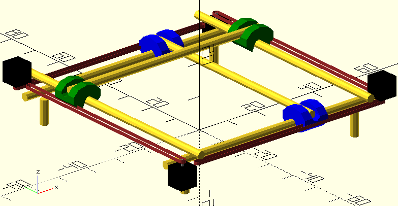
With that said, here’s an initial draft of what I was thinking of for the design (the trucks are the only printed parts shown, other than that it’s just the conduit and motors/belts for the XY part of the machine.
I believe it’s nearly as symmetric as the current design in terms of the corners - you will print two and two mirrored ones for opposite corners. The “mirrored” ones will have some changes in this case, however, to account for the motor facing upwards or downwards on neighboring corners to handle the X vs the Y axis. I was additionally thinking that the top and bottom could be symmetric (rotated 90 degrees, of course) in terms of the foot-mounting portion, as that might provide a nice mounting point for cable chain.
Potentially the corner printed material could largely be replaced by a single metal plate for each corner. A couple of U-bolts would hold the conduit in place on the top and bottom, and the motor and pulley could be mounted to the same plate. The only remaining printed part would be to attach the plate assembly to the foot post. This may or may not be a plus, as it is certainly less “mostly printed” and may not add extra rigidity.
As I currently have it, the belts are in line with the inner plane between the X and Y conduit ad the edge of the machine (so the higher belt is at the lower edge of the lower conduit and the lower belt is aligned with the upper portion of the lower conduit). This increases the symmetry at the corners, but it may require a different design for the X and Y trucks in terms of where the belt is held.
Hello SirNate0,
I like what I see here but lets set expectations first then focus on the good stuff.
I can’t speak for V1 (Ryan) but I wouldn’t expect these specific mods to get incorporated into the main design. First off Nema 23 steppers are overkill for the MPCNC. Since this machine is best when it is built small 24" x 24" max recommendation. It doesn’t need to push a ton of metal pipes. If you want a bigger machine then I would suggest a Low rider. And I think I have seen some mods for Nema 23s. (not sure). If you just want to have a small but strong machine then again Nema 23s are overkill. I have seen one of Ryan’s MPCNCs cut steel. So with that said I don’t think Nema 23s will be incorporated into the main design.
But as a user mod… I like what you are doing. I originally created this thread and have given it a lot of thought over the years. Personally I don’t like having to move motors around on a machine and I hate the cable management so I like the idea of relocating the motors to the corners. Do I think your design will work. Yes.
What potential Cons do I see?
Alignment of the belts. It will be difficult to get them aligned vertically and horizontally but your proposed solutions sound good.
Many Unique parts. It looks like you are trying to cut that number down but if this is just a user mod then it doesn’t really matter.
How will you control belt tension?
Like you said the machine will have a slightly bigger footprint.
This will require more belt. If the machine work area is 24" x 24" or less anyway this is a minor issue.
Stronger steppers may cause Damage to other parts of the machine.
Nothing in that list is really a deal breaker. But before we solve if it CAN be done lets first make sure it SHOULD be done. Why did you would choose the MPCNC for this? What size work area are you targeting? What materials do you plan to cut? Because it may make more sense to choose something more like the Low rider.
Ive been using an mpcnc with 8 Nema 17s 84oz. While it felt strong and could push it further than most it was overkill because it was strong enough to override the strength of the 3d printed parts so on more than 1 occasion almost took the machine apart so had to fix and reset calibrate etc. I was using a 2.2kw spindle. Fun, great learning experience but overkill. Now the Lowrider with nema 23s is a beautiful thing
Initially I was planning on a DIY design based around 2020 aluminum extrusions, but I later realized that my recollection of the size of the extrusion was off and that the cheap (i.e. 20x20) extrusion would likely be too flexible. As such, I would have to go with one of the more expensive larger extrusions, which would likely make the MPCNC a cheaper alternative, especially since I can use some 3D printers for free at my university. I also think the MPCNC just looks cool, which is a plus - it won’t help it cut, but it’s nice to have a machine look nice as well since it won’t be cutting 24/7. Further, it requires little in terms of actual hardware to put together, whereas a number of alternatives I’ve seen require you to have a pretty decent set of tools just to put it together (to mount linear rails and such).
I’m aiming for something around 2 feet on each side or a little under. Probably the project will have to wait a bit for me to move into a new place, so the exact size would depend a bit on the space available then. I’m not planning on working on full sheets of material, so I haven’t really been considering the low rider. Are there any advantages to that design for smaller build sizes like 2’x2’?
Materials would mainly be wood, possibly with epoxy resin inlays, and preferably aluminum as well (an aluminum chess set/aluminum dice would be really cool, but if it didn’t work it wouldn’t be a deal breaker).
And good to know about the motors potentially tearing apart the 3d printed parts. I hadn’t really considered that side of things.