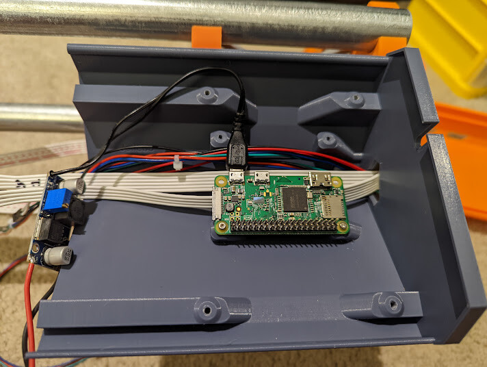
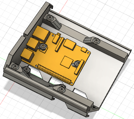
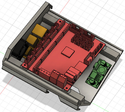
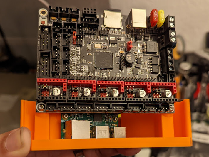
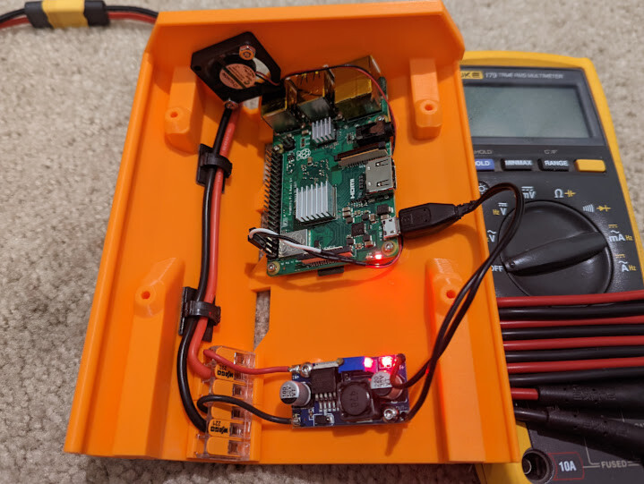
This morning I was determined to get this thing to move. The Pi ZeroW fits well in the space and has room for a micro USB power connector, but the GPIO headers and a little too close to the SKR to use standard dupont connections. I guess I could remove the header pins and solder directly to the PCB, but that feels a bit permanent for my liking.
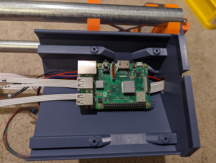
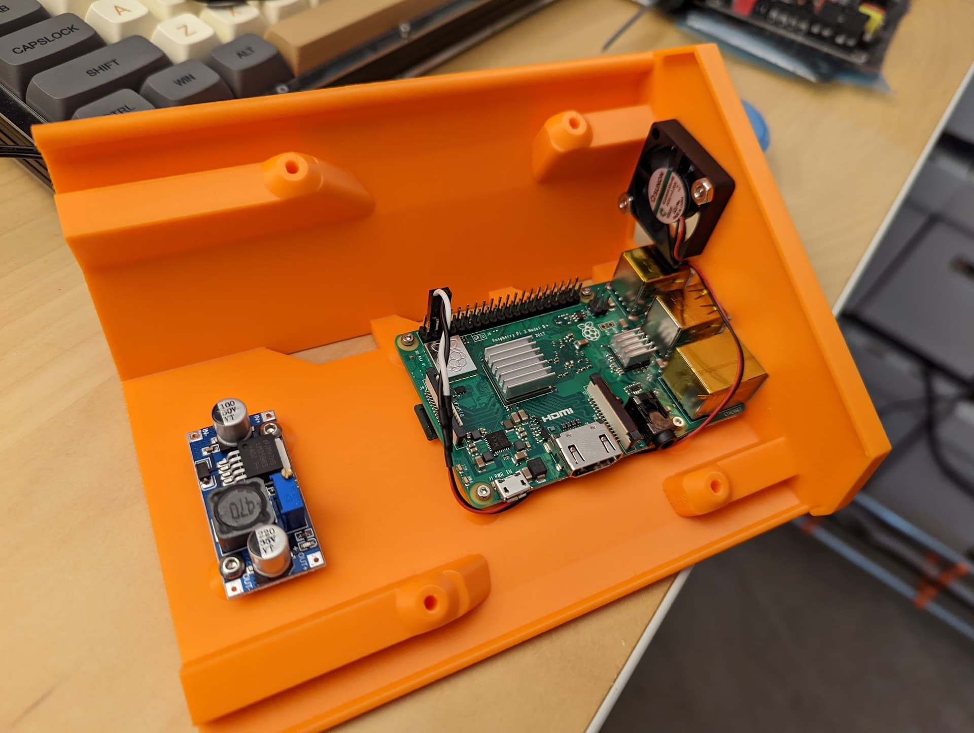
There were a hand full of times the load was a bit high so I thought I’d try a 3B+. The SKR’s 5vdc regulator seems to have enough extra mA to power the ZeroW, but the the 3B+ was throttling and under-volting so an external buck will be required. I’m a bit perplexed on how to power this thing since the micro USB power port is blocked and the BPIO header is too tall. I think additional remixing will be needed. Maybe add a couple of mounting holes for the buck.
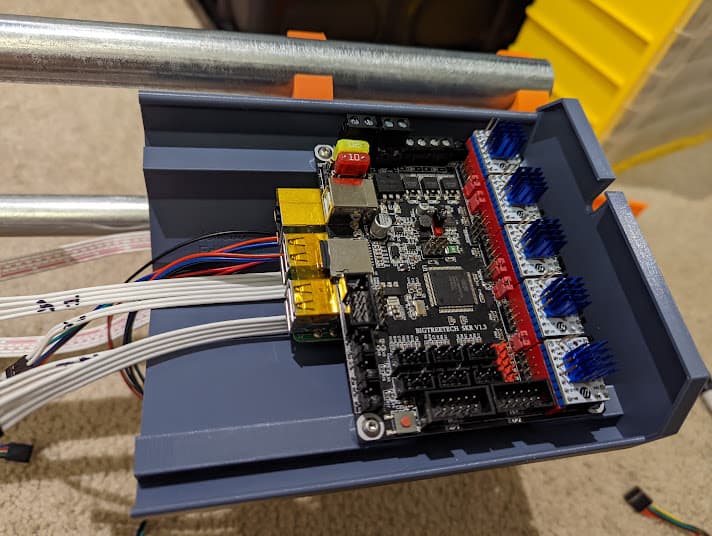
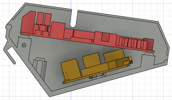
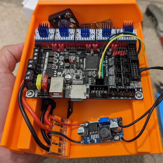
The SKR 1.3 fits like a champ! Though pictured, I had to pull the 3B+ out of the case until I can find a way to power and cool it in the existing case. @jeffeb3, any suggestions?
I am using an external buck/boost converter and I soldered straight to the 5V and GND of the input power micro usb. That way, the pi uses its own circuitry to filter the 5V a little.
It lives! Albeit a bit squeaky at the moment. I’ve been able to translate most of the V1 marlin changes into klipper (as far as I can tell) and it moves where I tell it to. Time to build a table I guess.
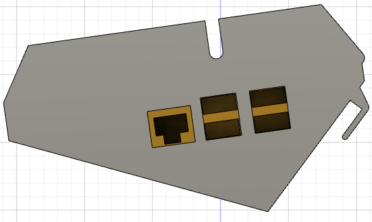
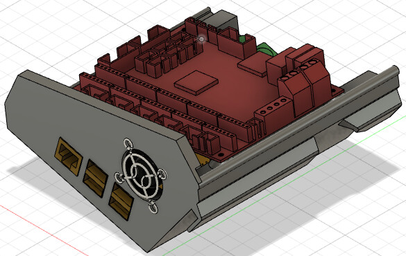
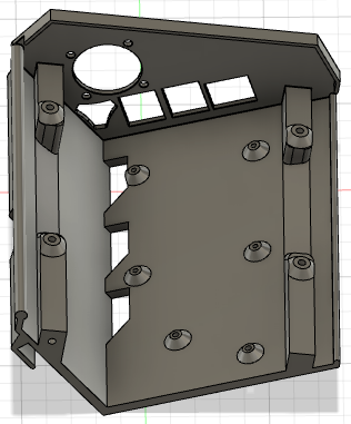
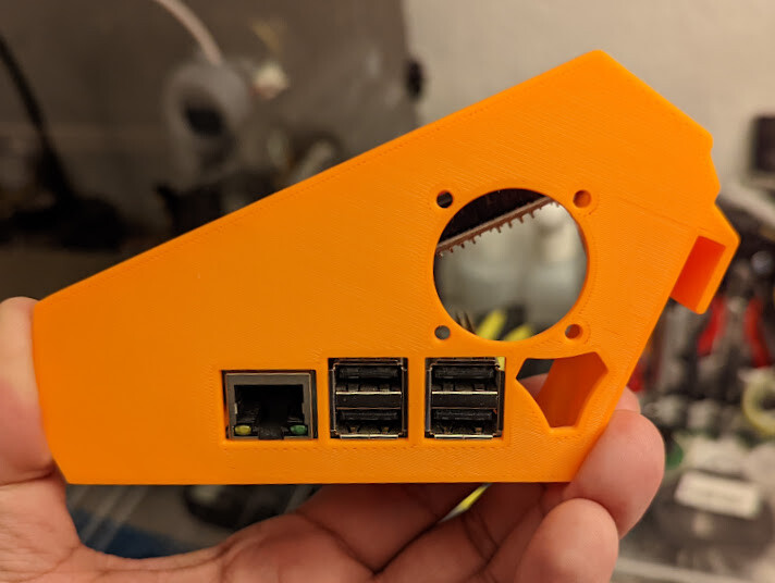
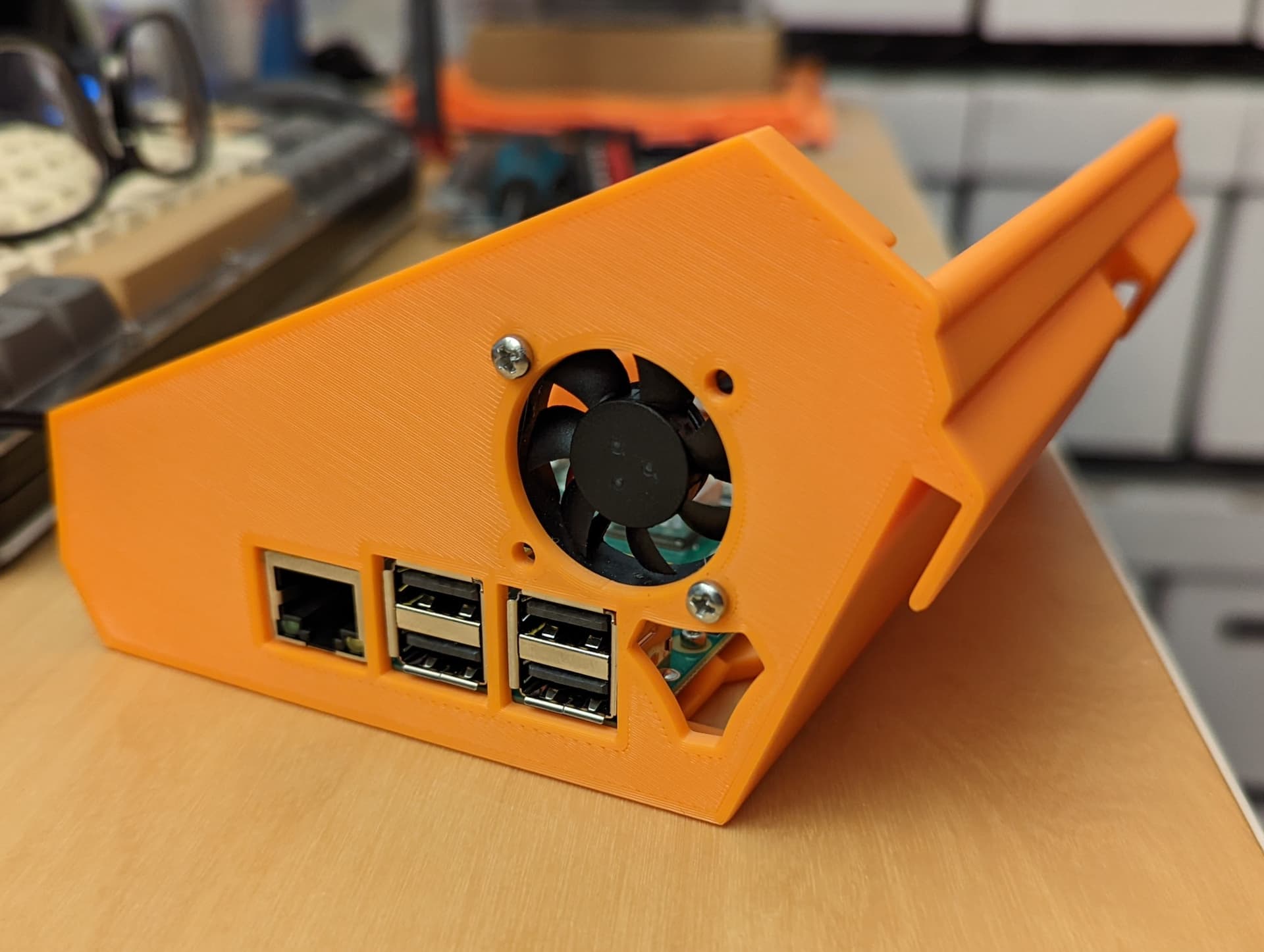
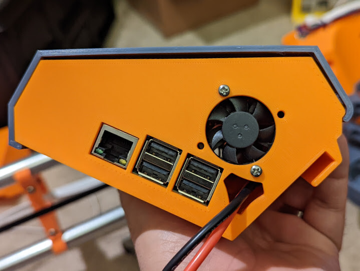
I’m thinking of spinning the Pi 180 degrees so the ports are externally available. This would also make the Pi’s SD card more accessible. Dropping the Pi down a few mm also would make the GPIO pins more usable.
Externally exposed USB ports can be used for cameras or in the case of Klipper, external “MCUs” for extended control.
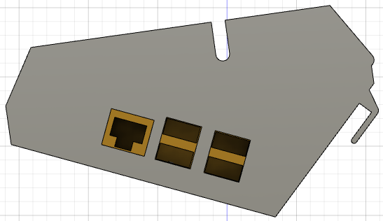
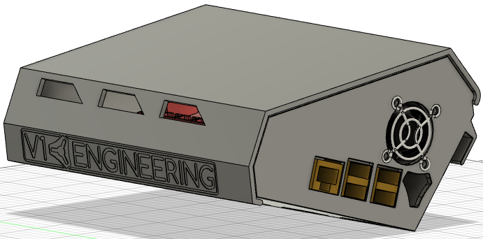
Because of the environment where this will be operating I would arrange for plugs/covers for the Pi USB and RJ45 ports to prevent dust and chip contamination. Should be easy enough to arrange, I think
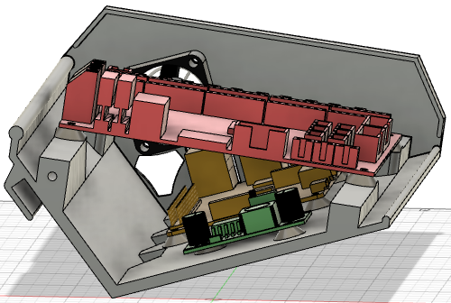
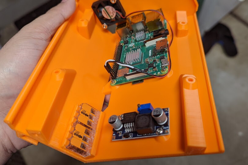
Plenty of room for wires and other bits. I think I’m going to replace the 5vdc fan (Pi powered) with a 24vdc that will be controlled by the SKR. The best part is I can switch back to UART control and forgo the giant USB connector.
Good suggestion, but in it’s default config the case is not exactly sealed. Granted I haven’t used this before, but the Pi ports are facing the “outside” of the machine away from the dust/chip generator. I get your point though, I’ll print up some plugs just in case.
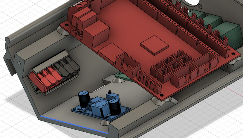
I picked up some Wago 221-413 connectors today to use for power distro in the case. Since I have already printed the case twice, I’m looking into mounts that I can glue inside of the case. Since I used ABS, I can acetone bond the parts together.
I ended up using a wago clip that orients the wires up instead of down. This makes using the leavers a little easier. I found some reusable clips that use VHB tape to fasten the silicon wires to the side wall of the case. I’m using a XT60 connector outside of the case since my PSU will likely be tied to the table in some way.
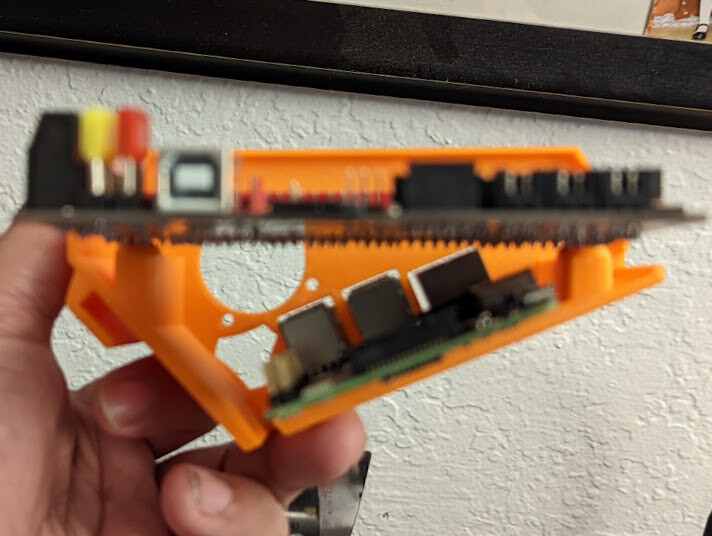
Next up, cable routing. There is less room for the semi ridged ribbon style extension cable than I thought. I’m thinking of making a set of JST to male dupont pig tails to hang out of the bottom of the case.
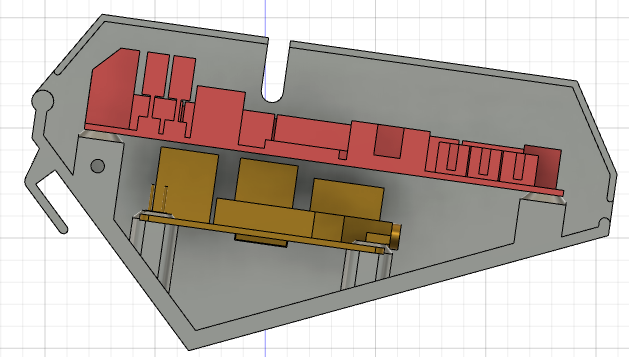
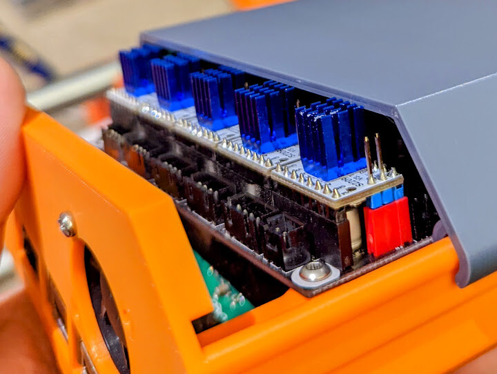
It’s not a deal breaker, just not ideal. For now there is just a little bulge and I assume it’s putting a little extra down force on the driver/socket.
I think I’m going to look for slightly shorter heatsinks than the ones that came with the drivers. Someone better at modeling would just make the case taller, but I do not have enough gray left on the spool to attempt re-printing the lid.
 I guess I could remove the header pins and solder directly to the PCB, but that feels a bit permanent for my liking.