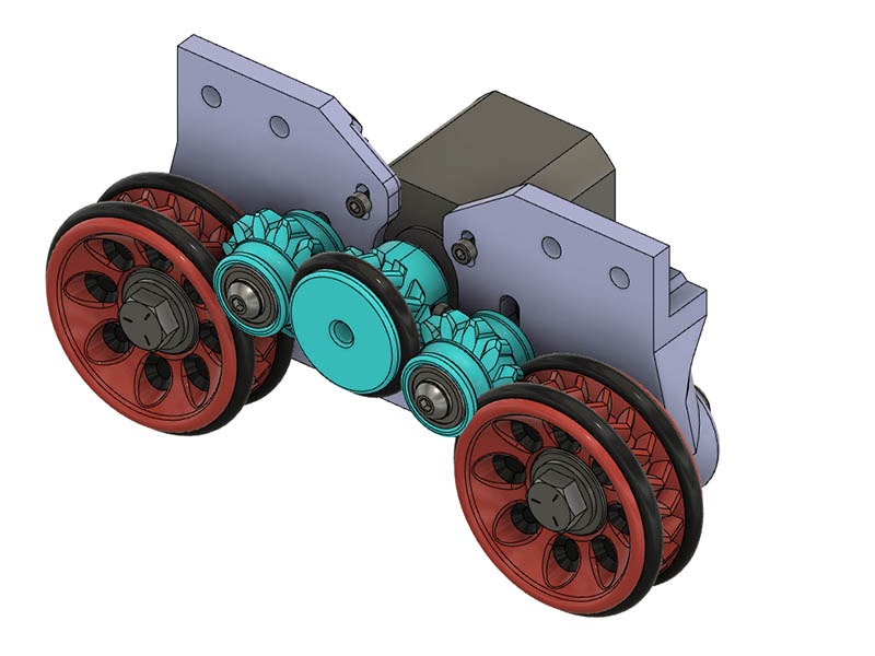
I redesigned the wheel drive to use double helical drive. Initially I made a 33T drive gear, but it was too wobbly when moving the gears around. I then tried a 16T drive gear & changed the wheel spacing to fit, but then it was not going to be possible to adjust the motor mounts screws after the wheels were on. The next option was to add another gear between the drive gear & bearings & think that will work. I also had the bright idea to add another o-ring to outer part of drive gear & o-ring grooves on the in between gear to keep them in alignment. Looks like it should work. I am also trying to figure out the
DEFAULT_AXIS_STEPS_PER_UNIT in Marlin for a geared drive. Does anyone know the proper method to calculate that? I found https://www.matterhackers.com/news/3d-printer-firmware-settings-stepper-motor-configuration this, but it is for extruder motor. I might just start with the settings for a 12T drive gear with GT2 belt & adjust it until correct if I can’t find a better starting point. I am using 12T drive & in between bearing gears & 22T wheel gear with a gear ratio of 1.83:1 Here is a current screen shot of the wheel drive design.
You really don’t have to know anything about the drive method. If it consistently moves a given distance when told to move X distance… simply tell it to move some convenient amount (i.e. 100mm, 50mm, etc… the bigger the better) and then measure how far it actually moved. Then simply multiply the currently stored value for steps/mm by (commanded / actual) and use that as your new steps/mm. For example, tell it to move 100mm and it actually moved 160… if the current steps/mm is 250, multiply it by 0.625 (i.e. 100/160) and your new steps/mm becomes 156.25. Rerun the test… command 100mm move and verify it moves 100mm. Do it as many times as needed to home in on the proper value.
I describe this in this recent post and also in my R&P MPCNC thread and verify by printing/engraving accurate rulers.
Let N1 be the number of teeth on the gear on your motor.
Let N2 be the number of teeth on your wheels.
Let D be the outer diameter of the o-rings on your wheels.
Let M be the microstepping factor, most likely 16 or 32.
Let S be the number of full steps per revolution of your motor, generally 200.
M is microsteps / full step
S is full steps / motor revolution
M*S is microsteps / motor revolution
N1 is gear teeth / motor revolution
M*S/N1 is then microsteps / gear tooth
N2 is gear teeth / wheel revolution
(M*S/N1)*N2 is microsteps / wheel revolution
(the intermediate gear doesn’t matter)
Let C be the circumference of the wheel, which is pi*D
The circumference of the wheel is linear movement / wheel revolution
(M*S/N1)*N2/C is microsteps / linear movement
or
(M*S/N1)*N2/(pi*D)
or
(M*S*N2)/(N1*pi*D)
This should get you close, and then if you want accuracy you should use @dkj4linux’s method to dial in the rest. Or you could do that from the start if you have an aversion to the math.
While I deeply appreciate those who can pencil-whip problems… math has never been my strong point. Even when I was doing this stuff professionally, I was more a seat-of-the-pants engineer… probably because I was a technician before I was an engineer
The astounding thing [to me] about the method I described is that while needing to know virtually nothing about the drive method, the components involved, or the source(s) of any repeatable error… the method rapidly “converges” to the proper steps/mm regardless of the magnitude of the error. Say you inadvertently left off a micro-stepping jumper and it’s off my a factor or 2, or 4, or 16… or used a 20-tooth pulley where it should have been a 16-tooth pulley… it still works
I will start with Jamie’s formula 1st & use dkj4linx method after that. I was going to use the method used for calculating e-steps after getting a starting point which seems like dkj4linx method.
The numbers I get for that formula are:
N1 12
N2 22
D 59.5
M 32
S 200
Using the 1st formula I get 62.77 & the 2nd formula I get 18.675
I will start with the 62.77 unless someone comes up with a better idea. I should be ready to test this again tomorrow. I still have to print 4 gears & another side plate. I cheated on not having to reprint 1 sideplate & made a plastic drill jig to drill the 2 slotted holes for the new bearing gears.
I tested it today & having that extra gear in between is too difficult to get a good mesh. I used 62 for the steps per unit & drew a 10mm line to start with & it was 7.5mm, so that 1st formula seems to be a good starting point. The gears didn’t go well, so that number might be closer to 10mm if the gears meshed well. I am going back to the single 33T drive gear. I have a couple of ideas to make that large gear not wobble. In any event, it is not nice meshing of the gears with just that one gear to adjust. That 62 will be about 23 with this larger drive gear.
It appears that with the 33T drive gear there is not enough torque to turn the wheels. I adjusted the vref from my initial .47v on the DRV8825 to .65v & then .91v & the wheels still will not turn. The drive gear will turn when the wheels are not engaged. I also tried it with the wheels off the ground to see if they would turn. I either need to go to a smaller tooth drive gear or go back to my original belt driven method. I might shorten the wheel offset & see if I can have motor mount access holes placed in the wheels. It is funny that my 1st idea worked the best. I have some 105zz 5x10x4 bearings I might try for making a smaller idler pulley with the belt design.
That wouldn’t help. He’d have more torque turning the wheels, but the wheels would need more torque to move the machine. There’s currently almost a 1:1 ratio between the motor pinion teeth and the distance the machine moves. All the gears in the train are meshed, so they don’t change anything.
How about moving the motor up (or down) and add another small pinion, driving the currently driven gear? Or one central gear that meshes with both wheels, driven by a small pinion?
If I made the wheels bigger I would need bigger O-rings. For the 3-4" ID O-rings with 3/16" thickness they are $14-$15 per 25, or $3 or so for 2 of them. I need 8 for the wheels. That is from Grainger supplier. I was trying to avoid spending any more money on this, but that is a possibility. I am going to shorten the wheel spacing to see if I can get what I have to work. Thanks for the idea.
I tried putting a gear between the drive gear & wheels, but I could not get a good meshing of the gears. Maybe the single helical gear would mesh better than the double helical? Since my original idea worked the best, I am going to back to that one unless something else looks better. I just have to wait for the real GT2 belts to arrive. In the meanwhile I am going to test a small idler pulley design to use with the GT2 belt.
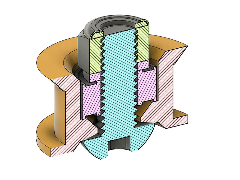
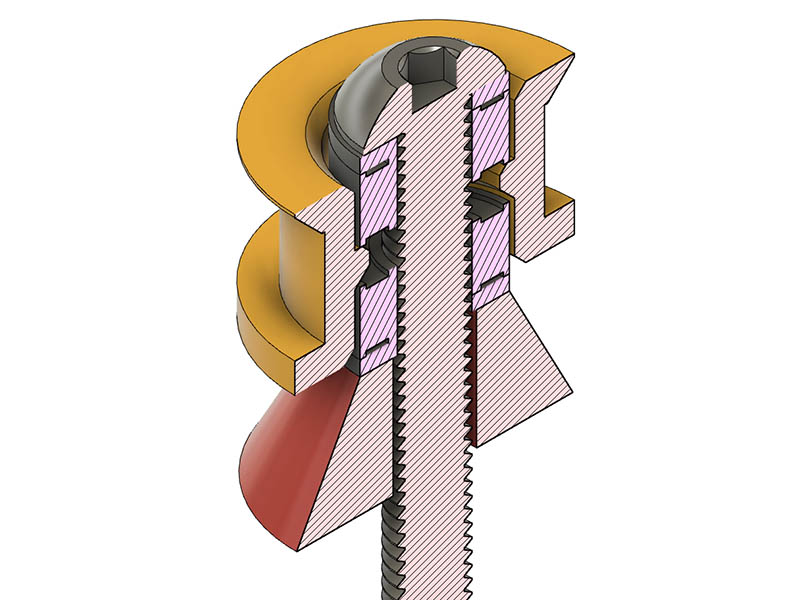
Rubber bands sounds like a good idea. Can you get thick wall rubber bands, or maybe doubling them up to get them thicker. The thickest ones I have are about 1mm thick. If I make a .5mm indent for them that would probably be enough so only the rubber touches the floor. After reading Robin’s comment seems like my 1st method is probably the best since it worked with the TPU belt & since I ordered those belts a few weeks ago. Here is my mini bearing idler pulley idea. The outer most diameter is 18.5mm. I am seeing if one bearing will be good enough & kept the overall width as short as possible. Might need a little longer screw.
Hmm that diagram looks like youre clamping the inner race to the outer race and it might not turn. A short protruding tube could allow clamping the inside race from both sides and an inside ledge on the pulley similar to what you have could allow the pulley to be captive but not clamped, so it would still turn freely.
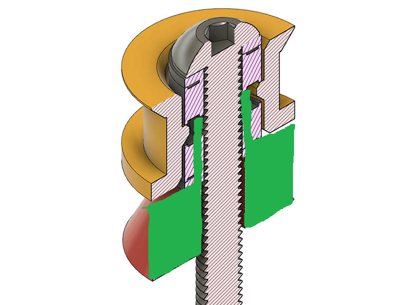
I realized that also after looking at it more closely. Thanks for the confirmation. I am not sure what you have in mind for the short protruding tube. I was going to redo it using 2 bearings in each of those idlers. I was also thinking about the side roller bearings I was working on when designing it & forgot I have plenty of room height wise. It is the Diameter I was trying to keep as short as possible.
But it doesn’t matter, just a throw-away idea. I like your solution better because the pulley is properly constrained axially instead of floating and possibly (probably) rubbing on one side.