Router/bit as z probe, no alligator clip (DW660/RT0701C)

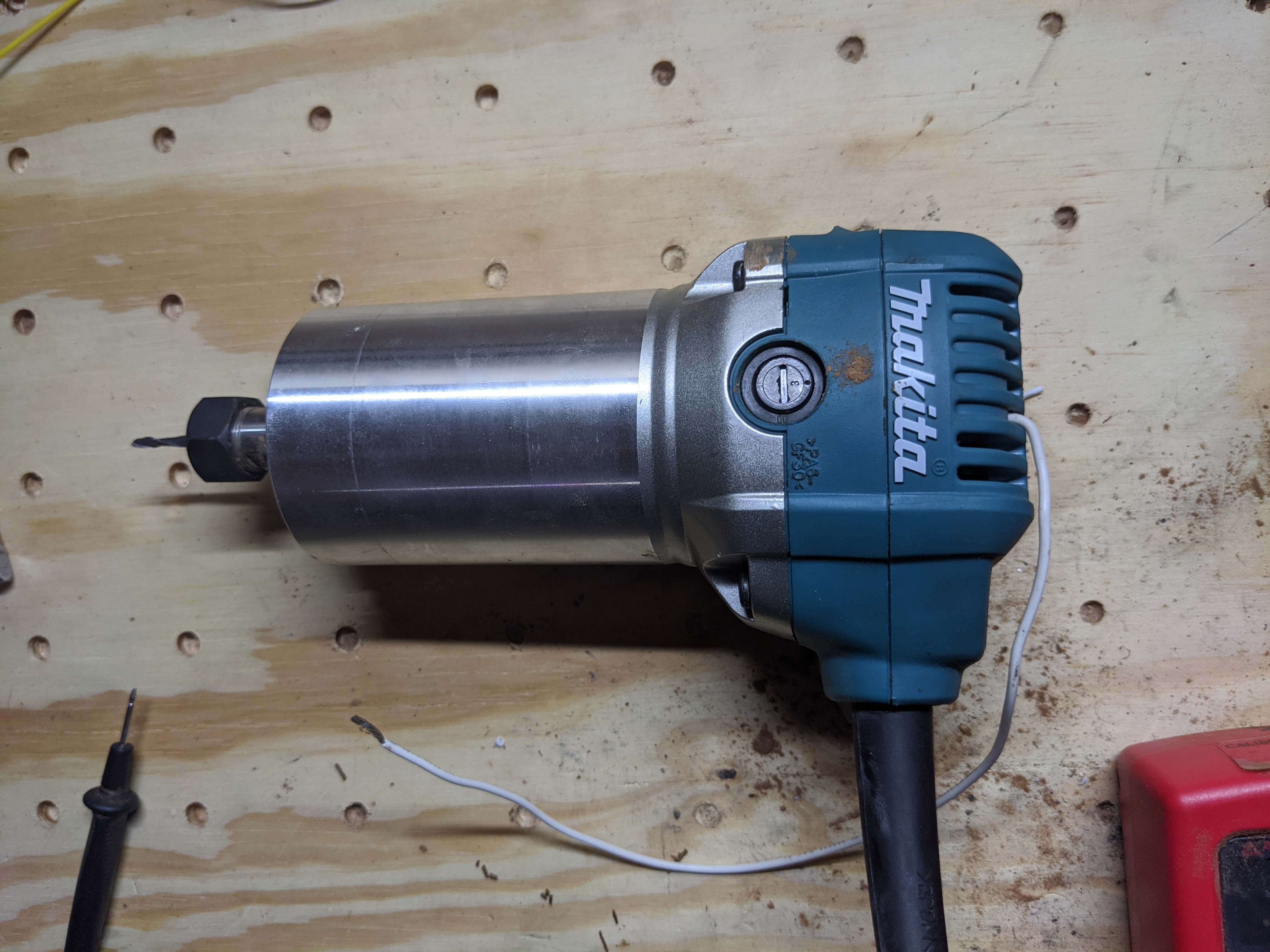
I’ve been using mine like this for about a year with a Makita RT0701C. I hit a stopping point on my primo upgrade until more parts show up and caught a glimpse of one of my old DW660’s and decided to see if I could do the same on it. Best I can tell it works!

I’m going to give instructions for both but all I took pictures of so far was the DW660 last night, so I’ll start with that one.

Disclaimer: you’re taking stuff apart and doing weird things to it. I’m not responsible if you blow up your house doing this. I’ve also not even used the DW660 like this myself, but I see no reason it won’t work as well as it has on the Makita for me.

I’m also bad with instructions so good luck.

The idea is simple. You just need to find somewhere to attach a wire to something stationary that has continuity all the way through to the bit. Then you don’t have to mess with alligator clips on the bit for z probing anymore. You only need the plate.

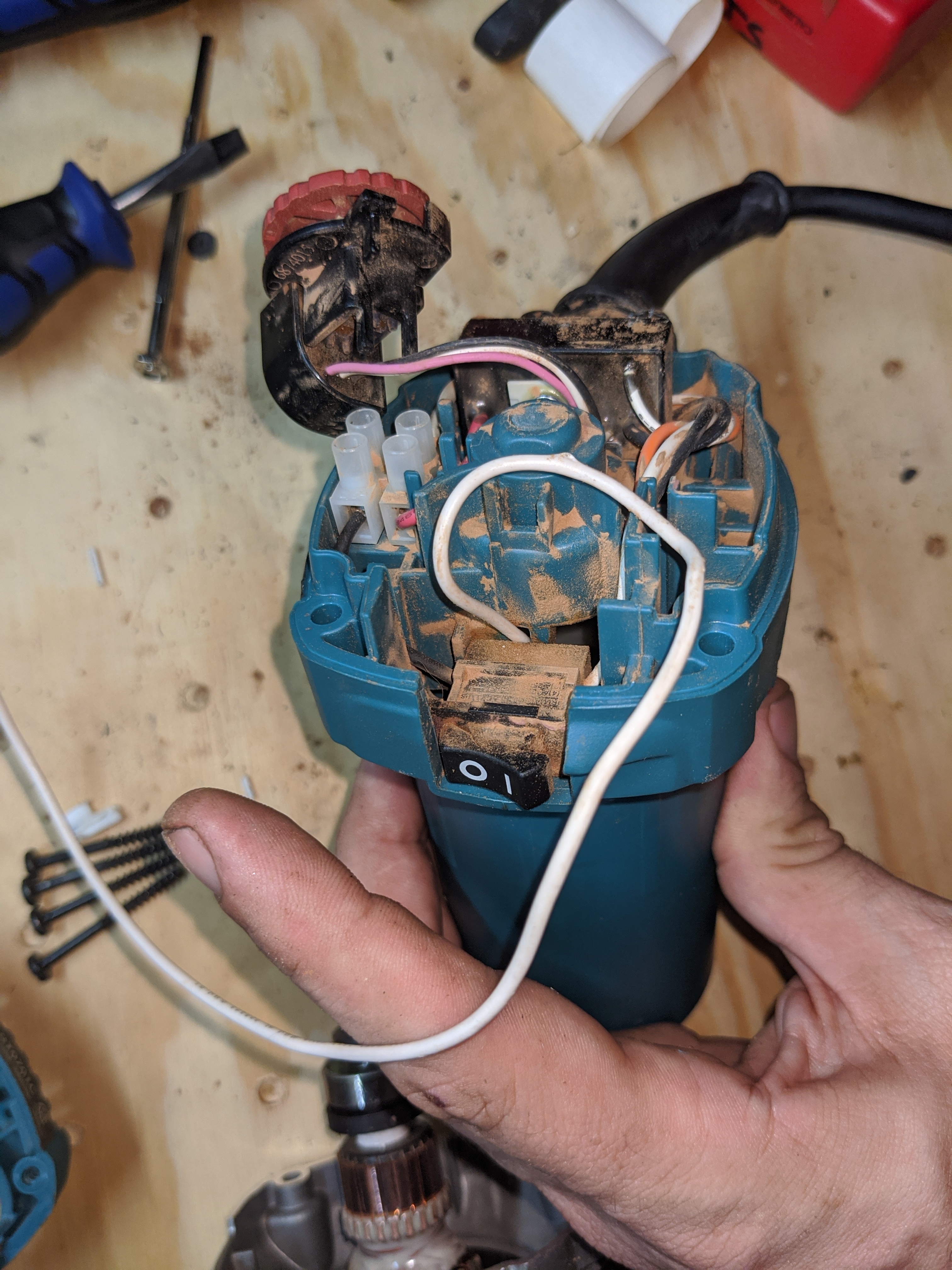
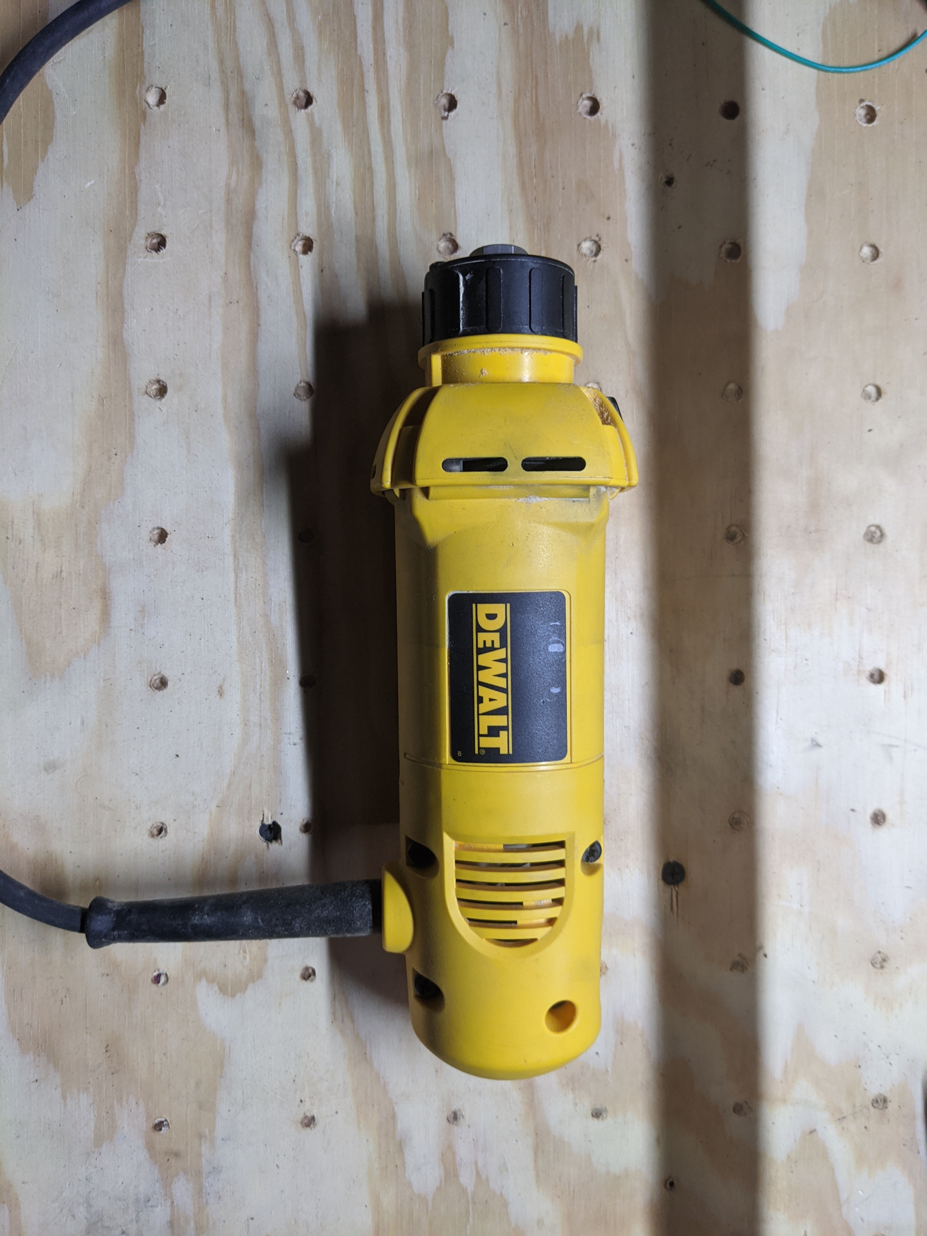
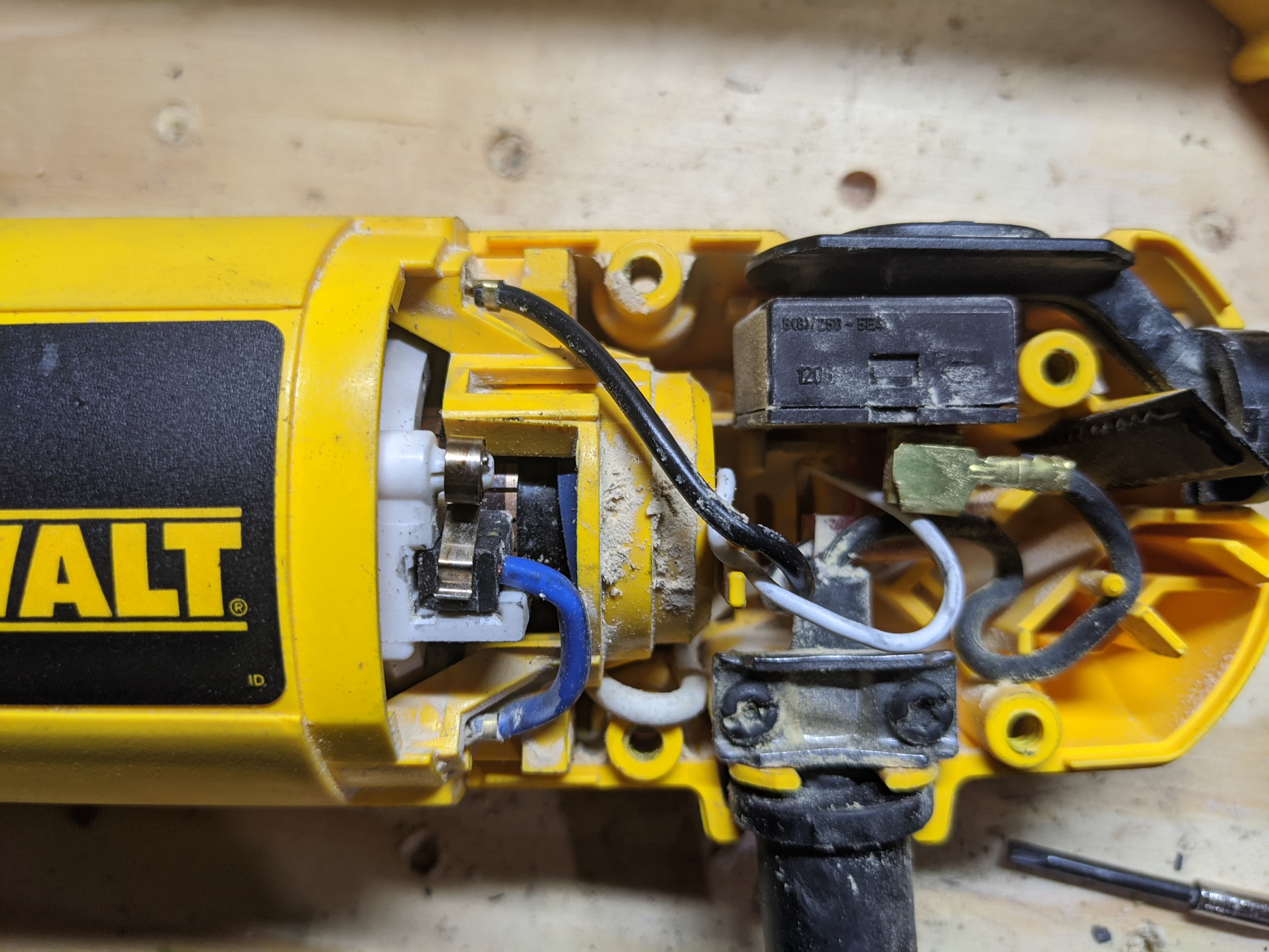
Behold, an uncorrupted DW660

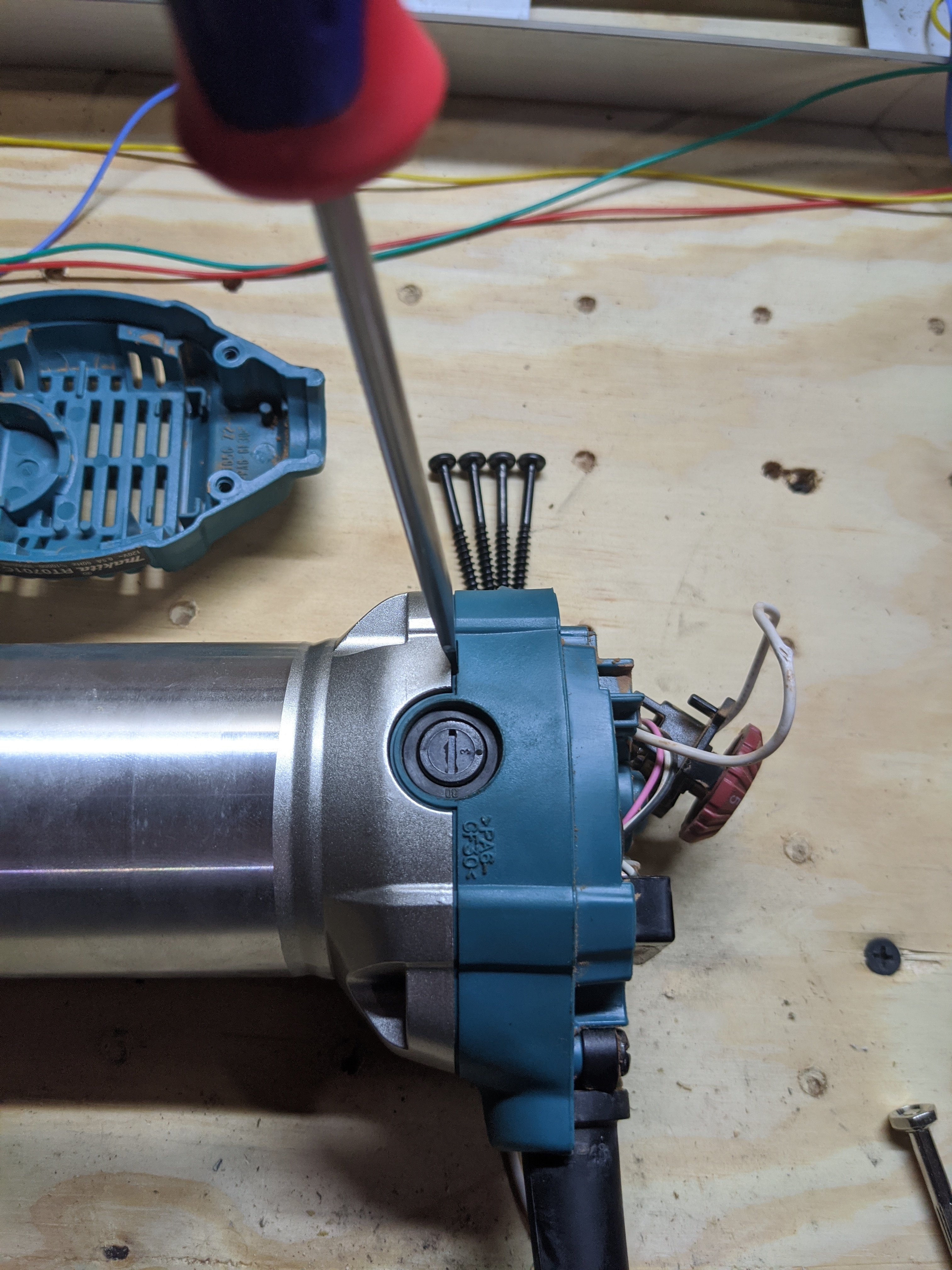
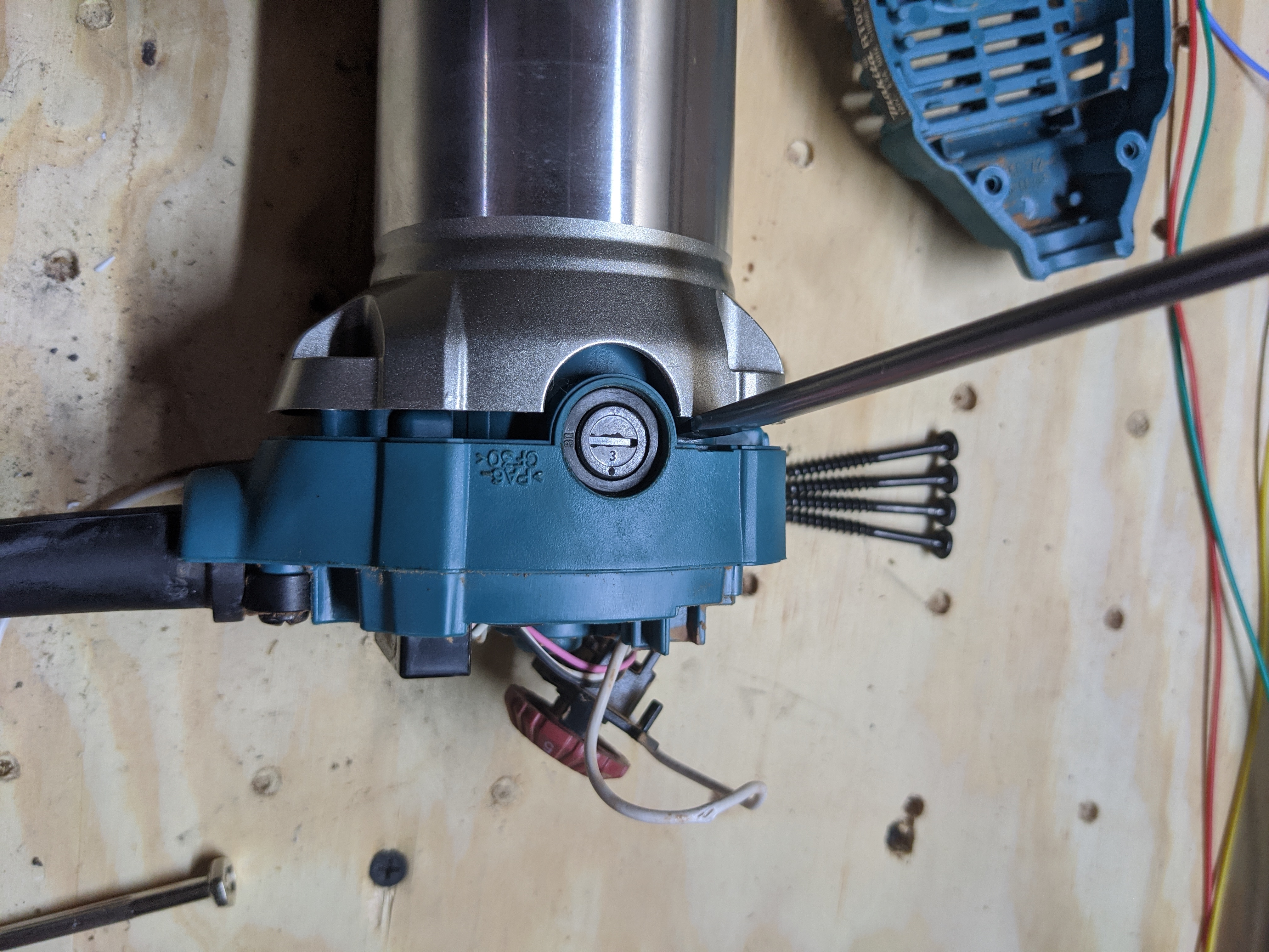
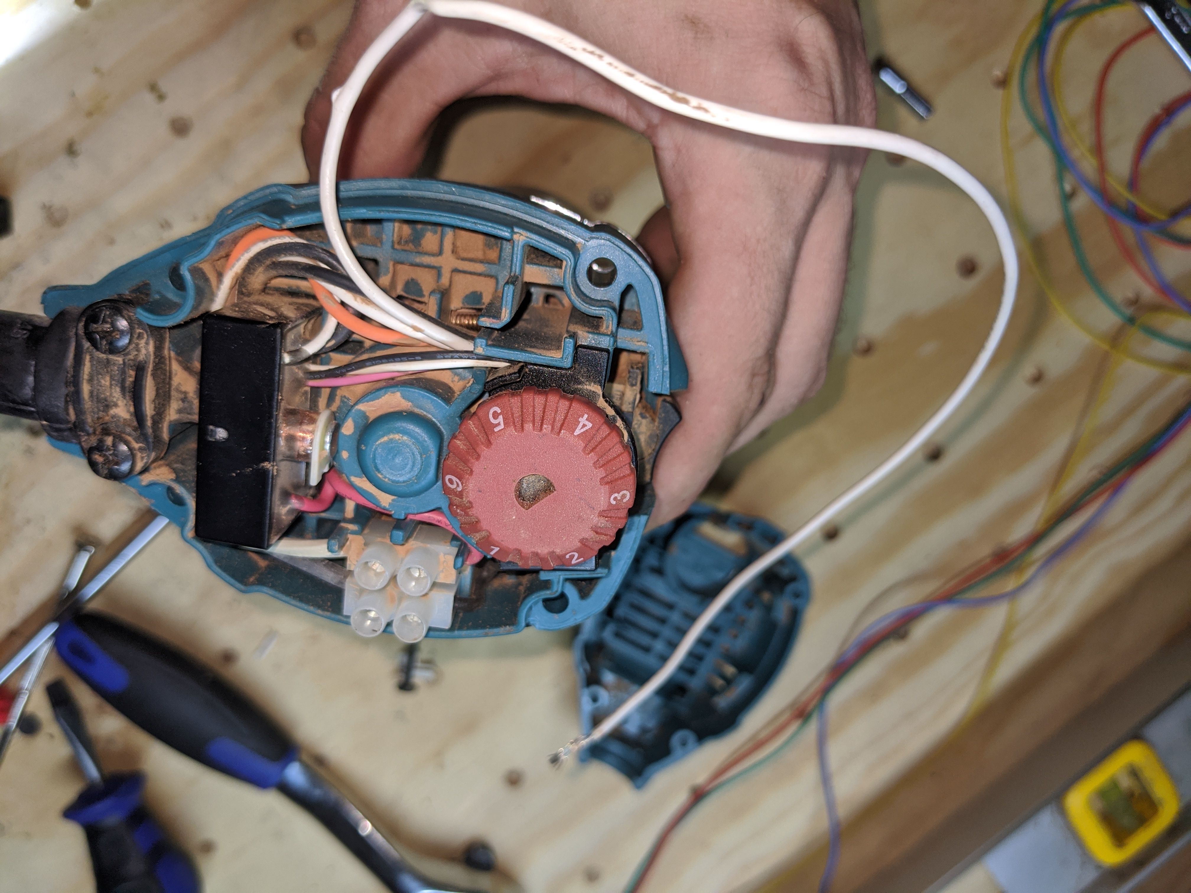
You’re going to have to do some minor disassembly. First get the top cover loose. There are four star head screws you have to remove.

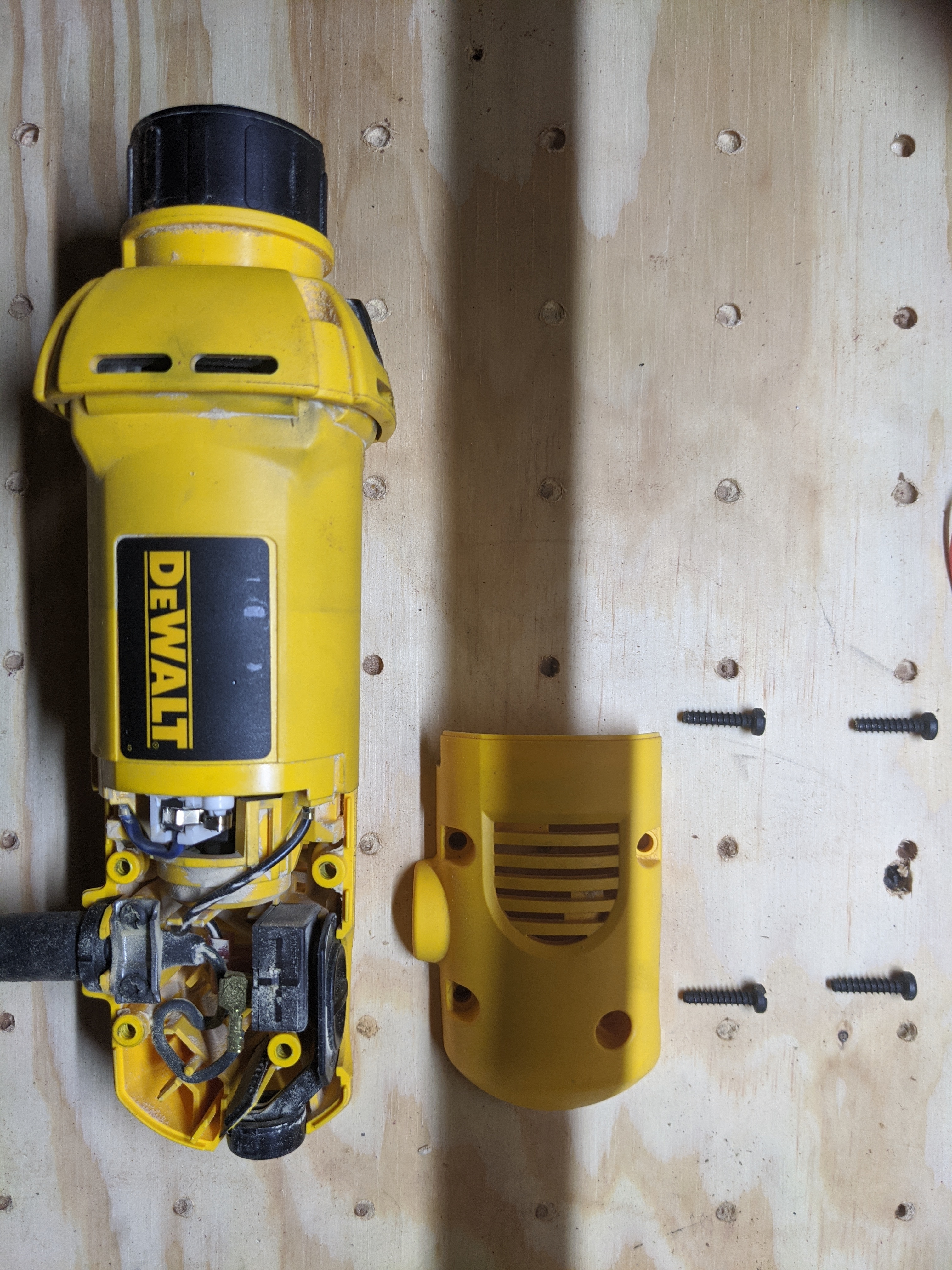
Next you’ll need to get the guts out. There are four more screws that need to be removed. You do not have to remove the locking mechanism to do this. You’ll see I did in some of my pictures. This was only because I wasn’t sure how it came apart yet. Best I can tell it wasn’t necessary. Let me know if I’m wrong. If I am its just two more screws. Careful, there’s a spring in there.

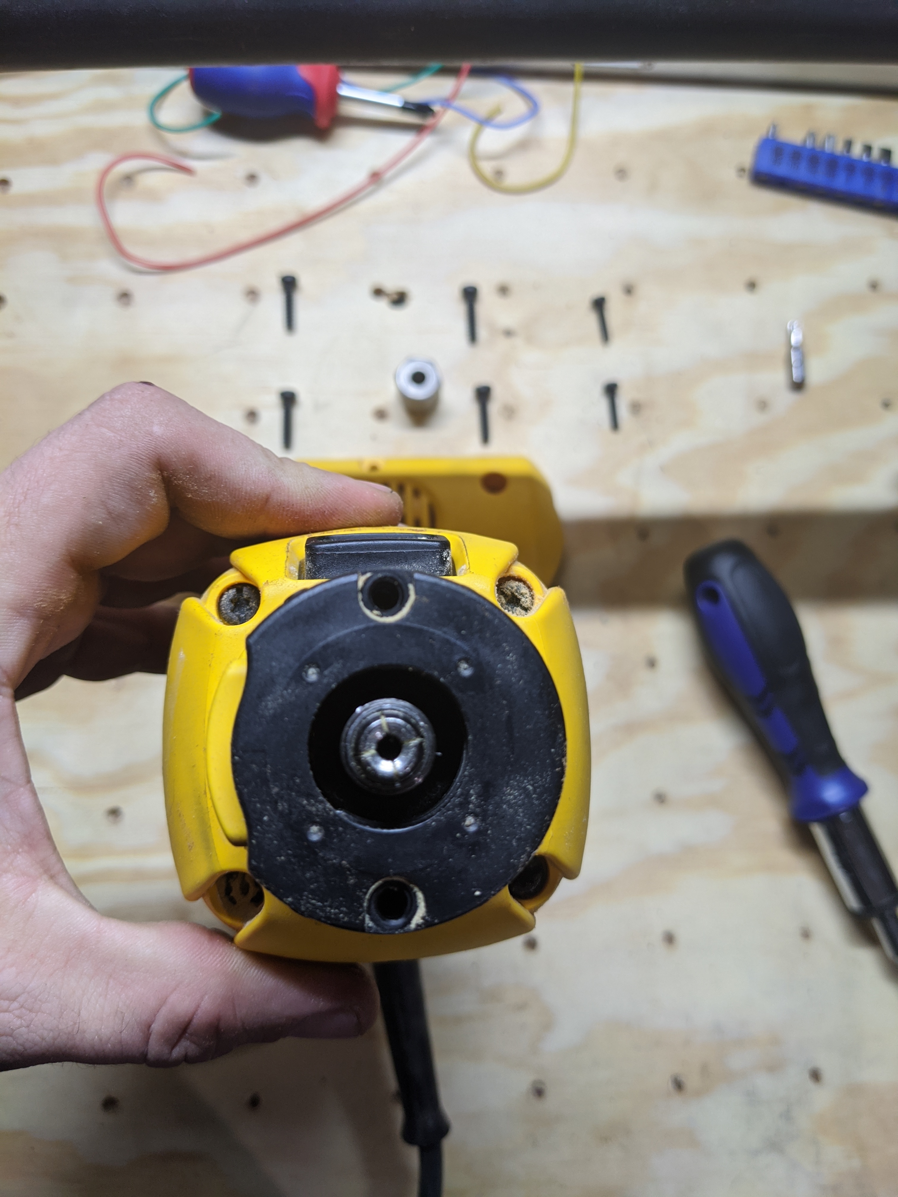
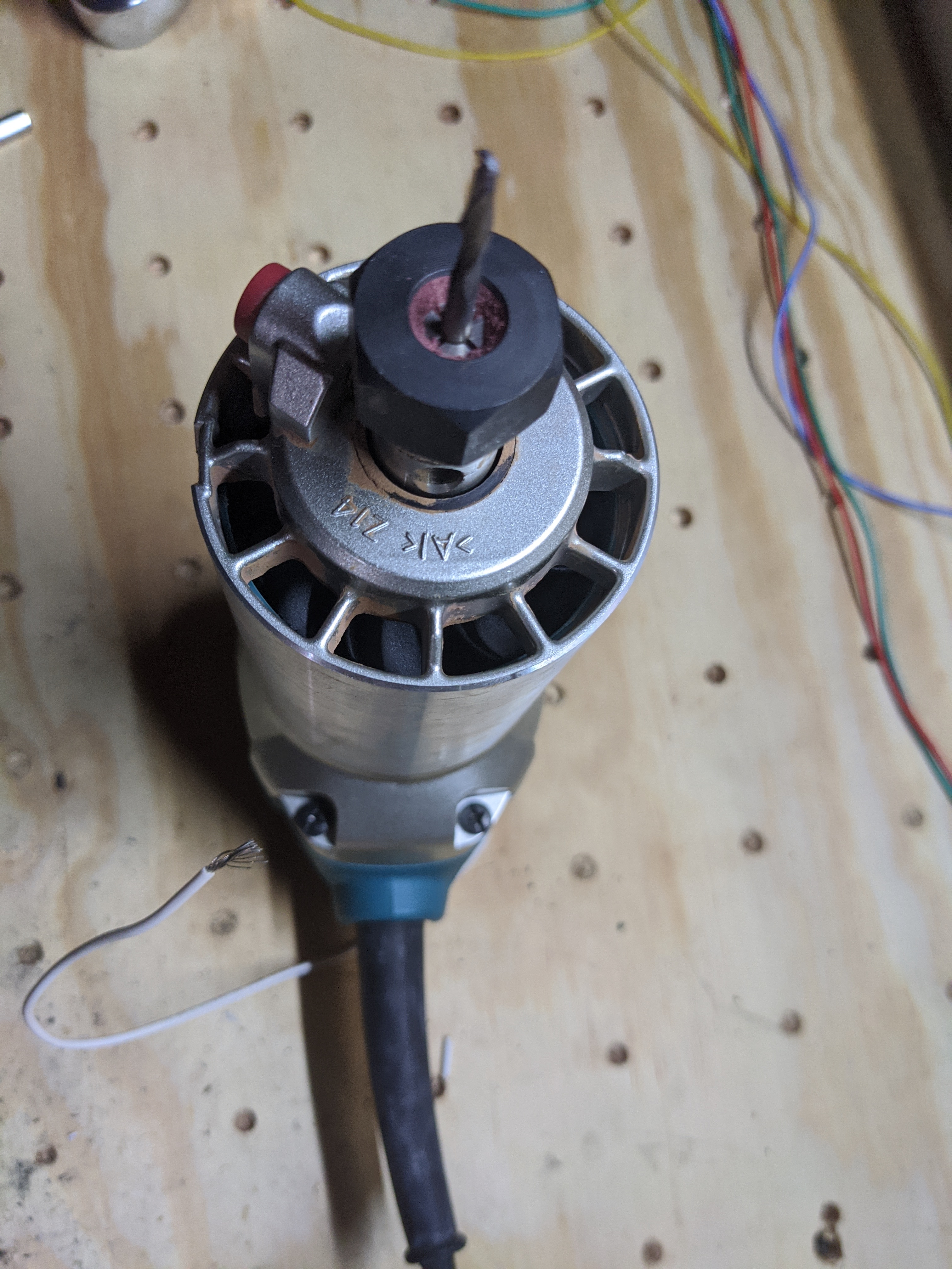
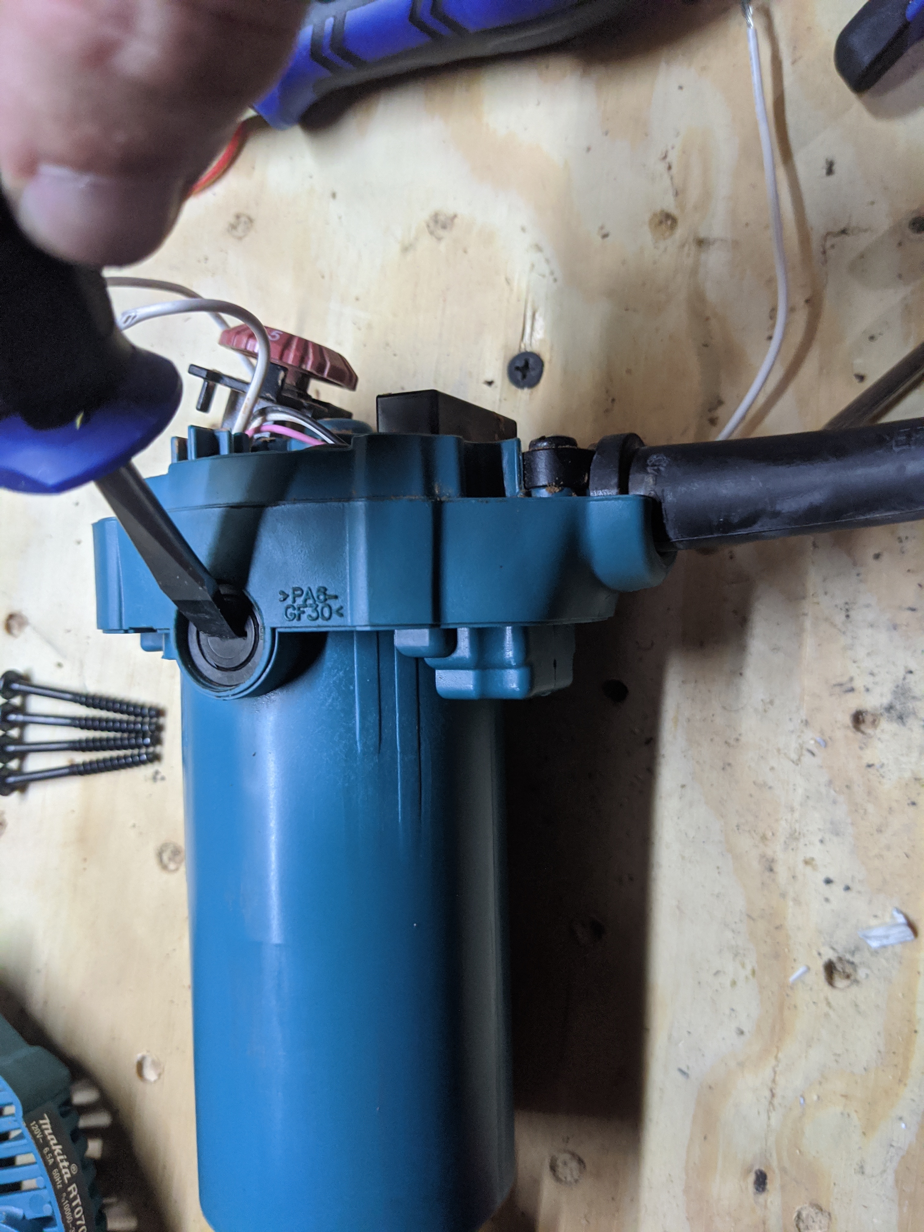
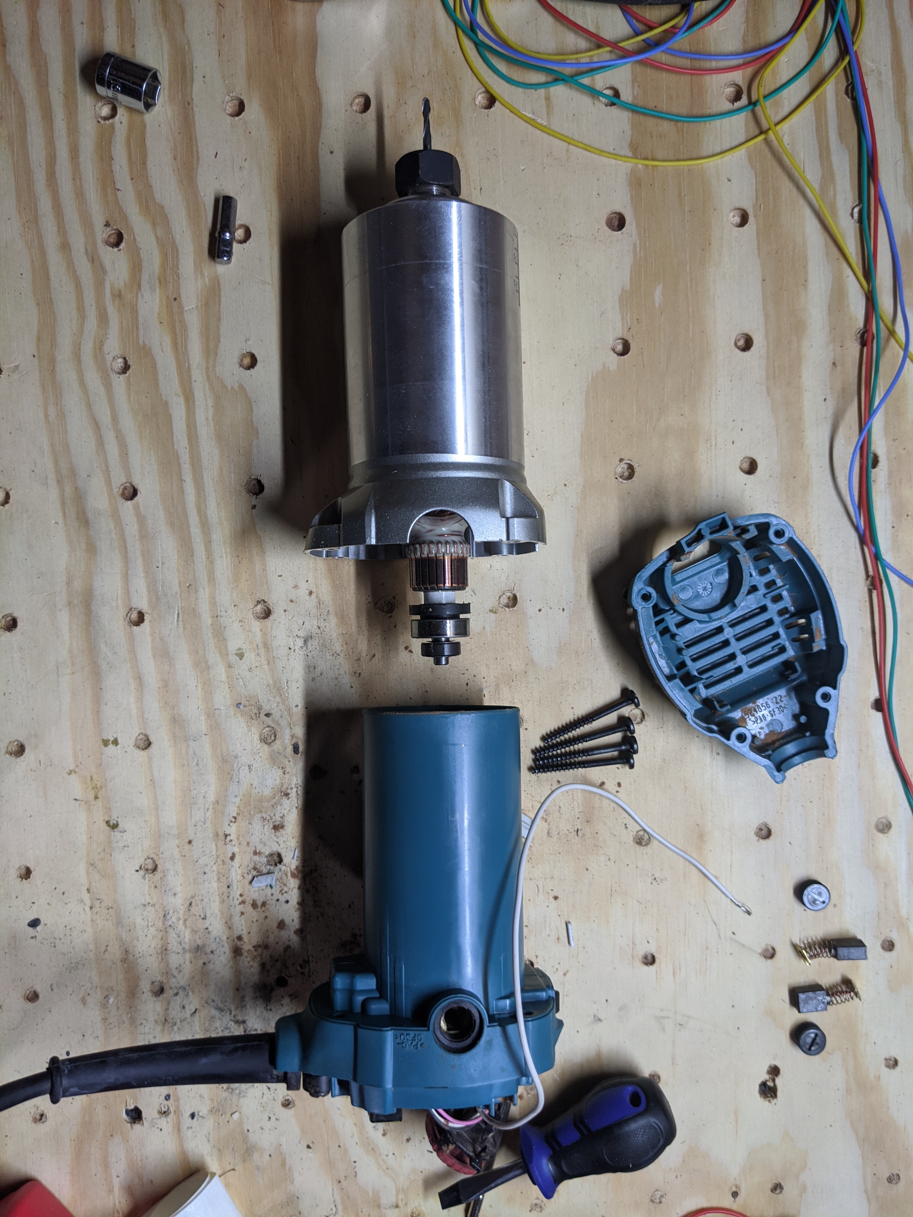
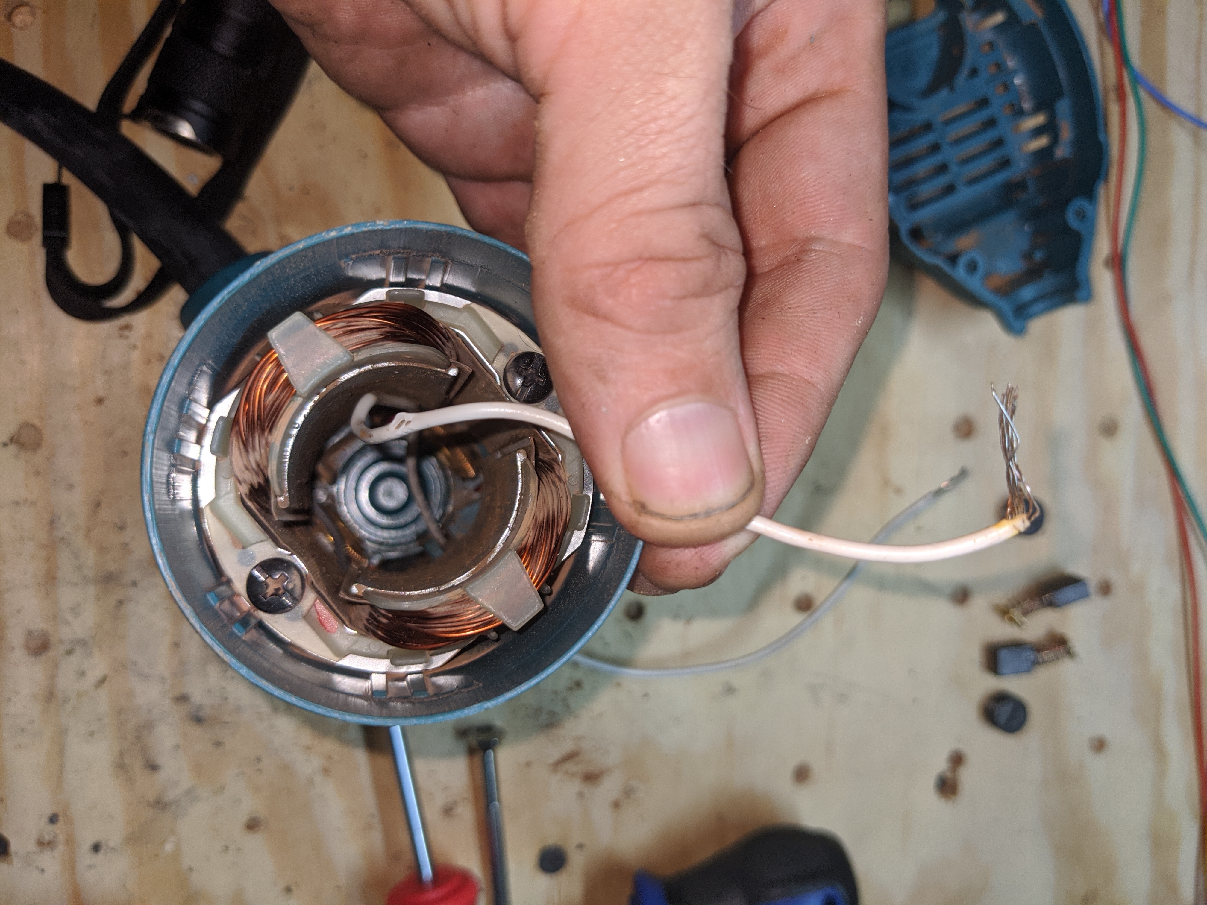
Now you should be able to slide the rotor out.

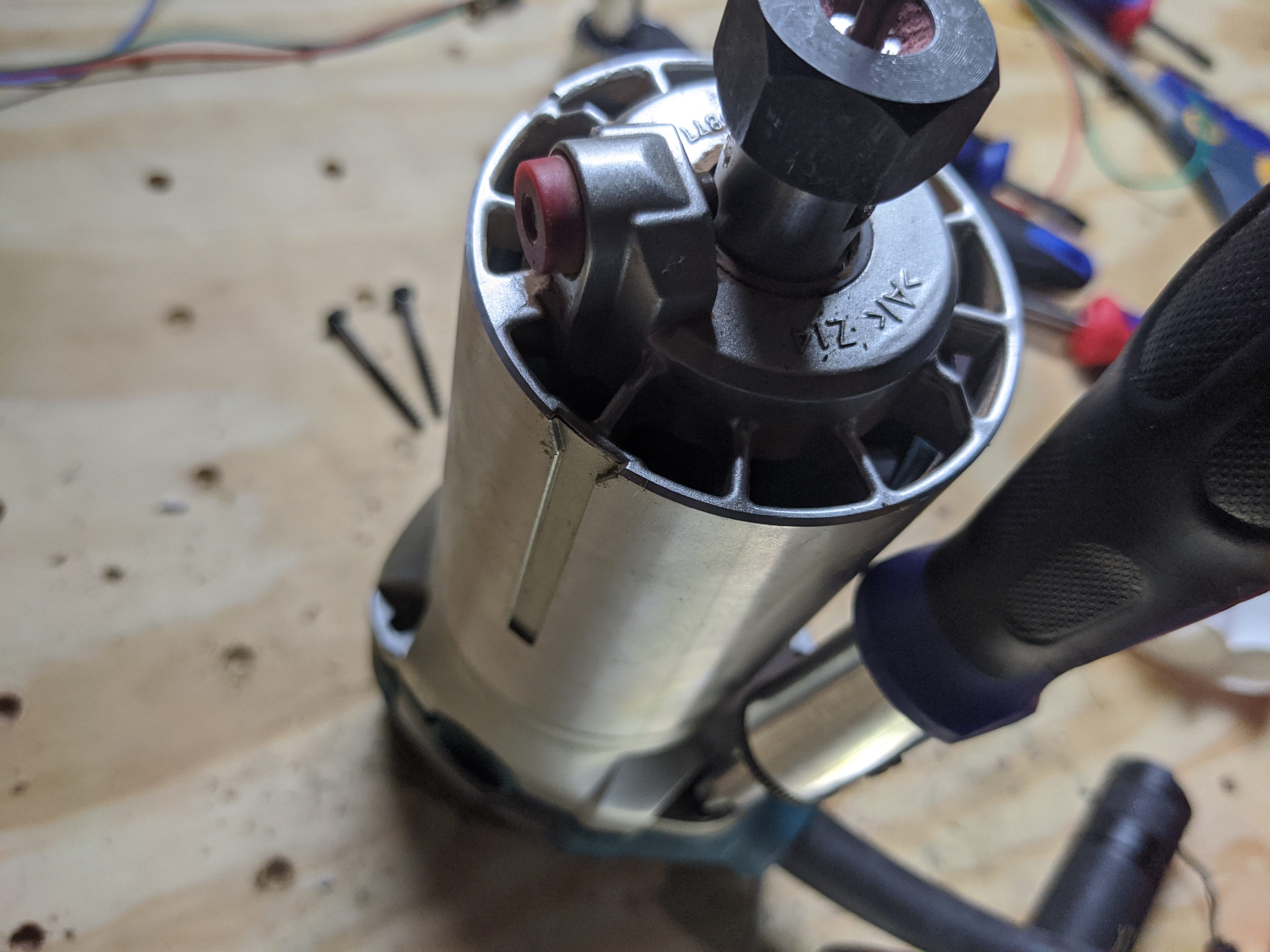
At the end of it is a bearing and a blue silicone…thing. It might not come out with the rotor. If so you’ll have to push it out. Small screwdriver should do the job.

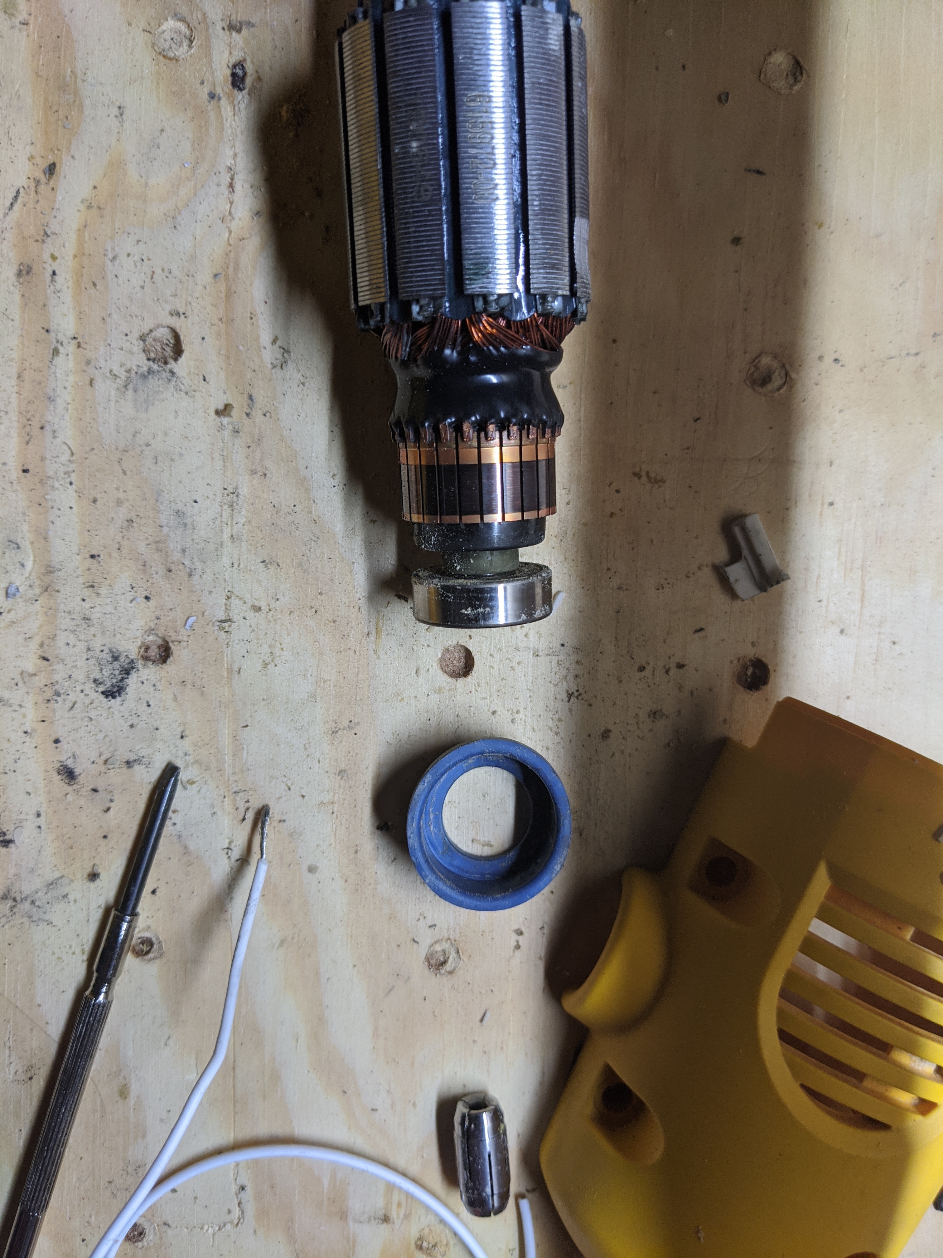
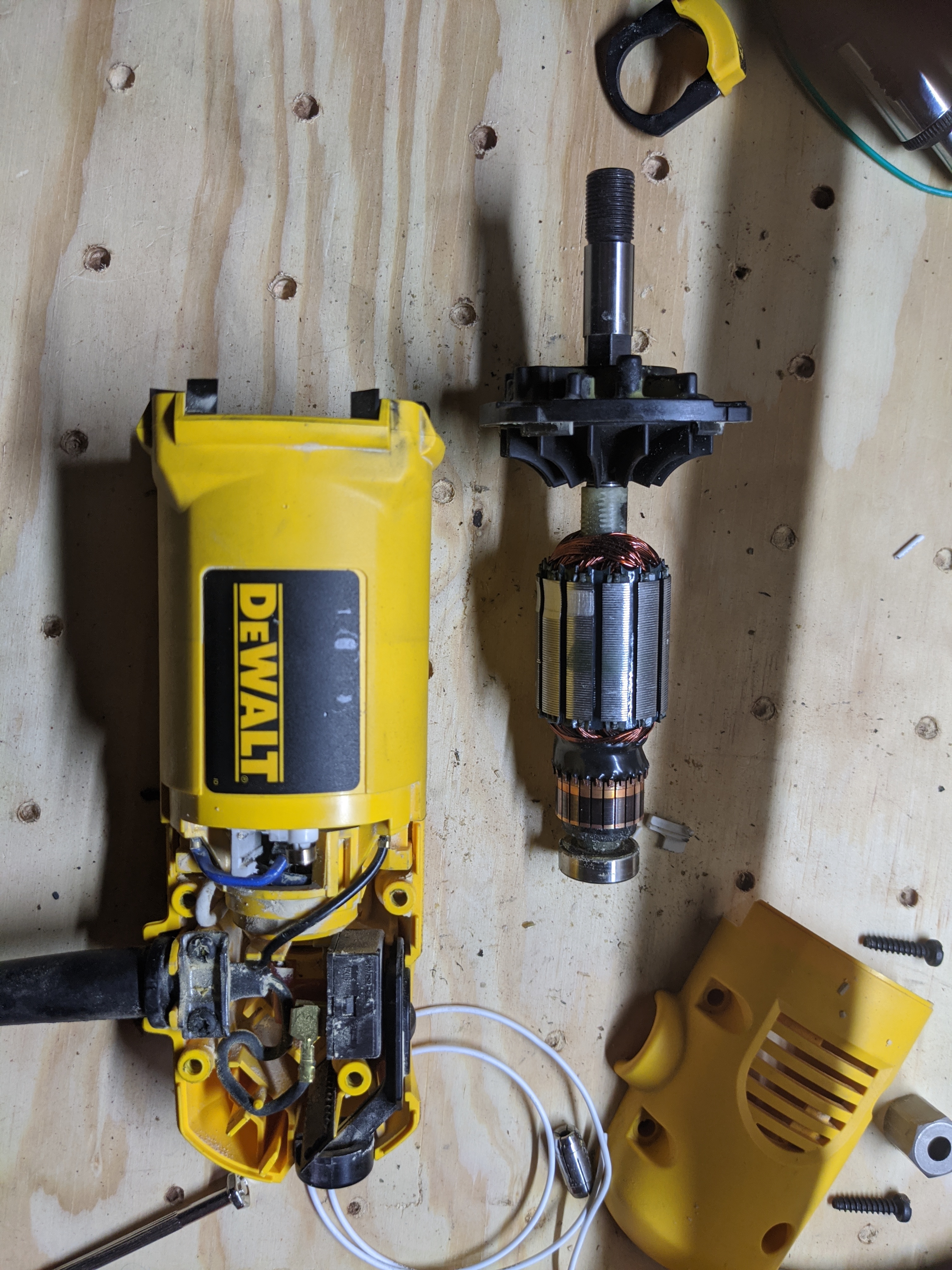
This bearing has a conductive path through the bearing, down the shaft, and then through your bit. So now we just need a wire. Wedge the stripped part of the wire between the silicone thing and the outside metal edge of the bearing.

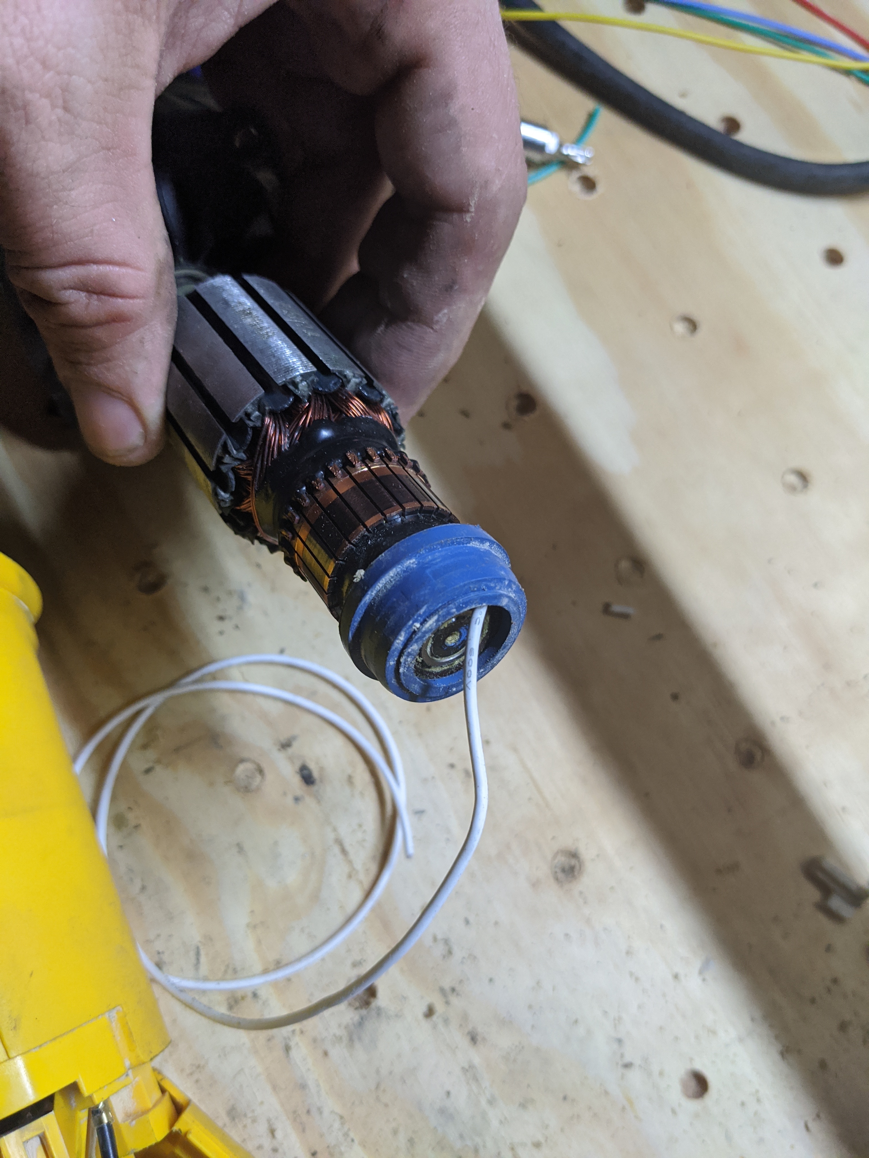
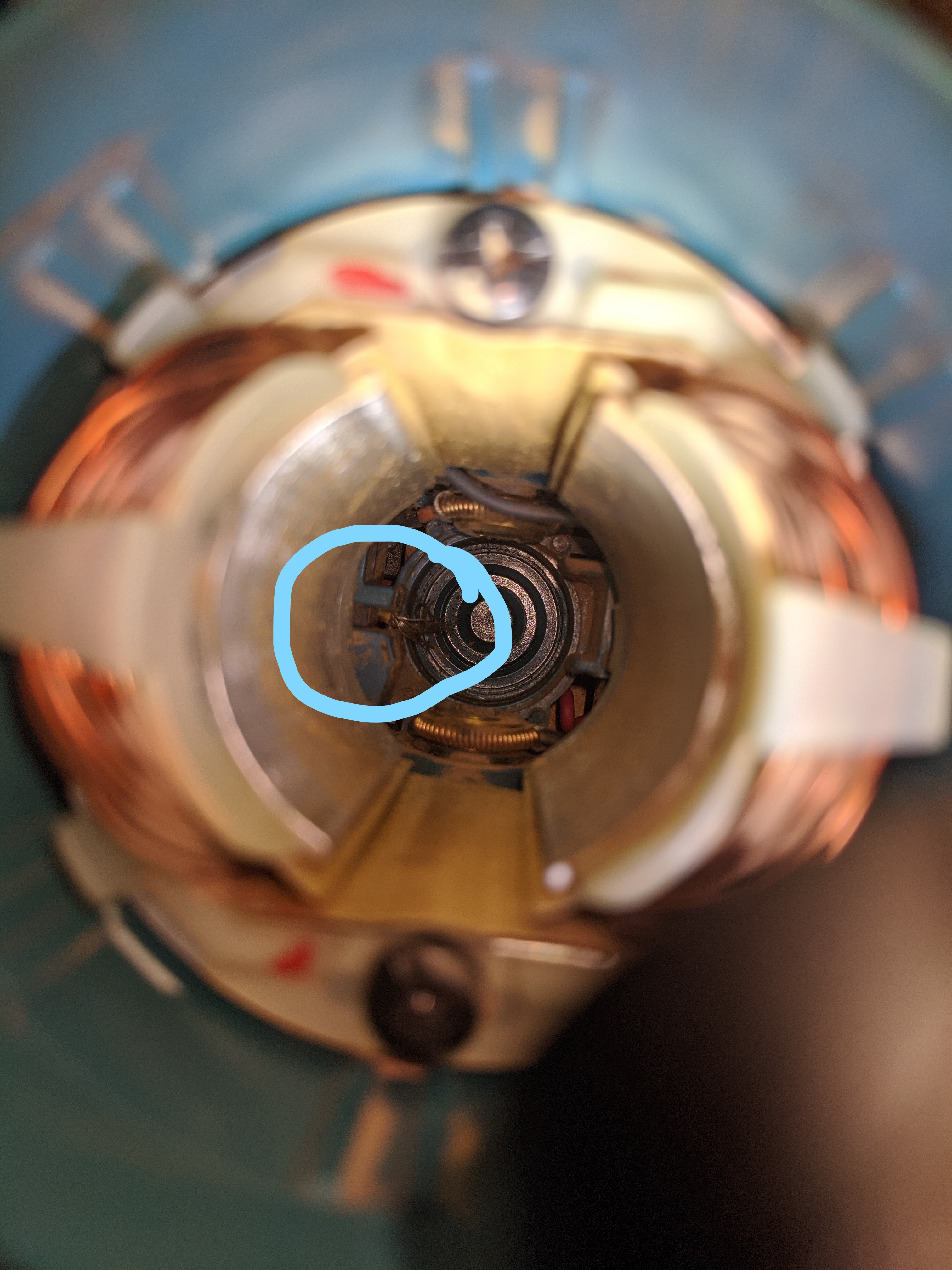
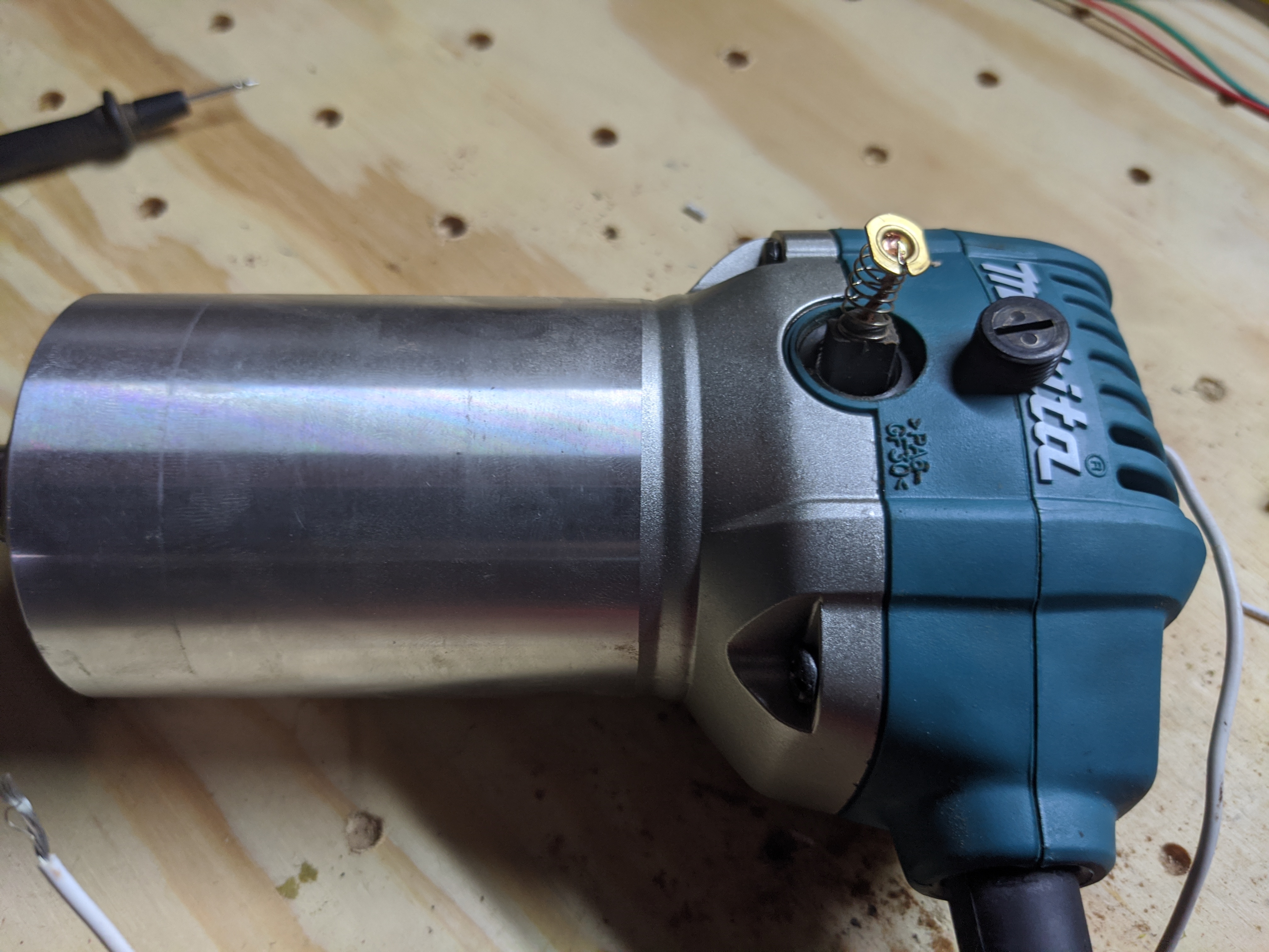
Carefully feed the wire back up the DW660 body. There’s not much force holding it in right now. Follow it with the rotor and start putting things back together.

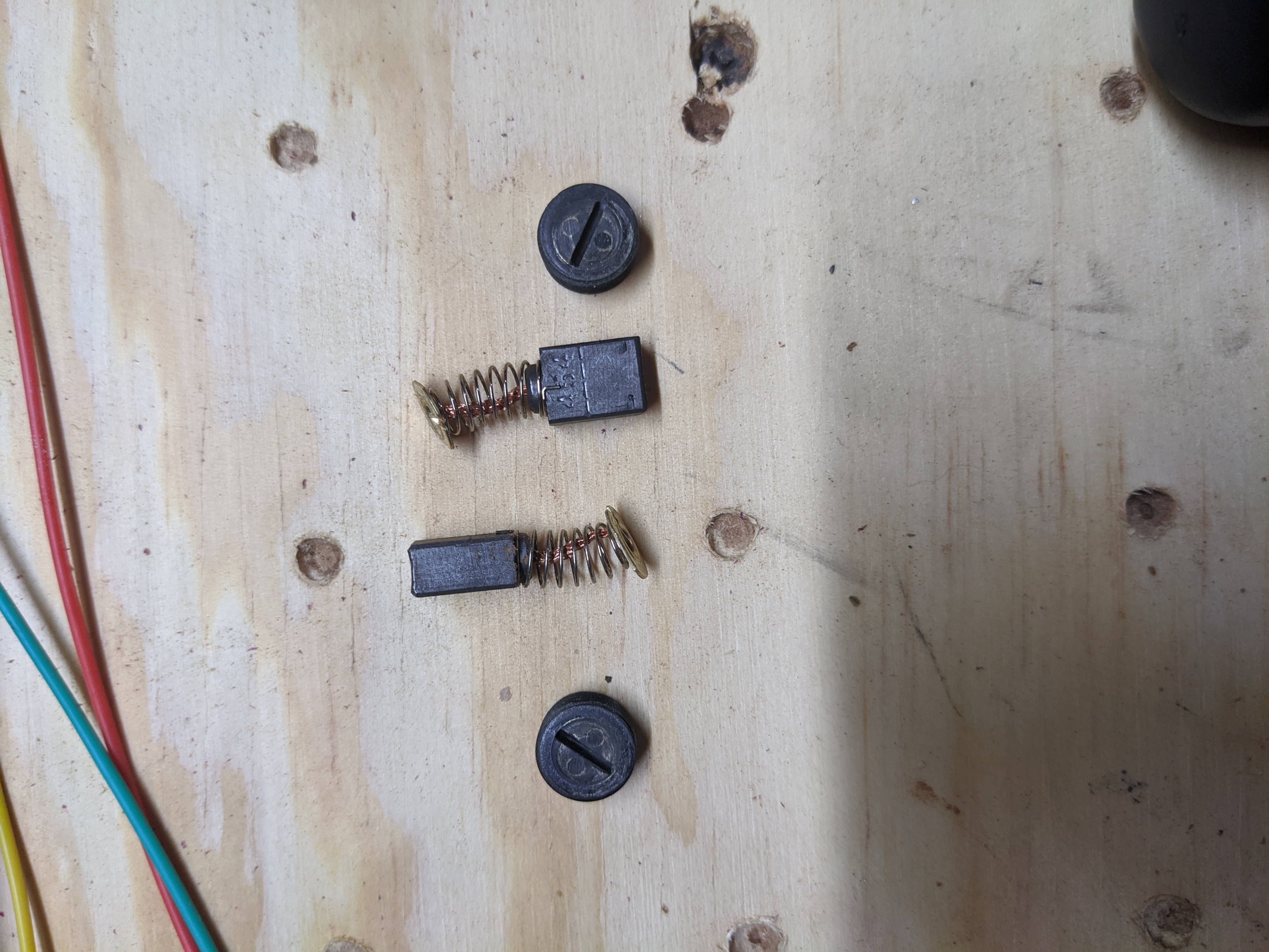
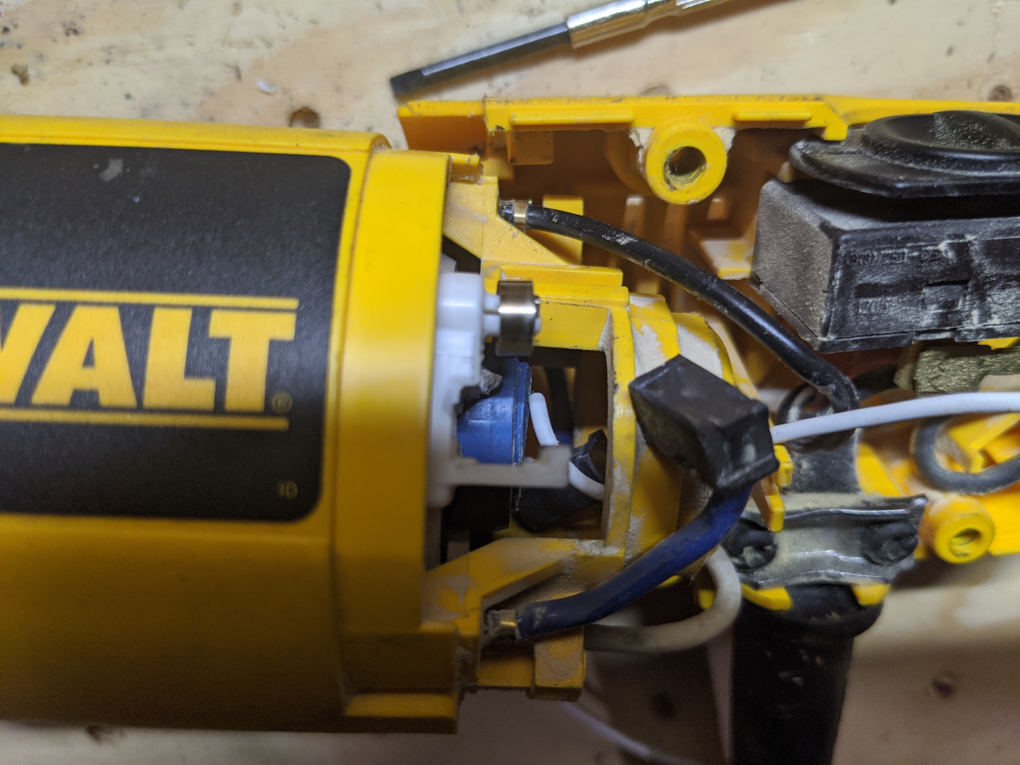
WARNING when you start to slide the rotor in you should feel nearly no resistance. If you do, you’re hitting something. Don’t force it. It’s likely the brushes and you’ll have to pull them back out of the way to slide the rotor in. There are two brushes, the other side of the cover is also loose so you can remove it to get to the back one.

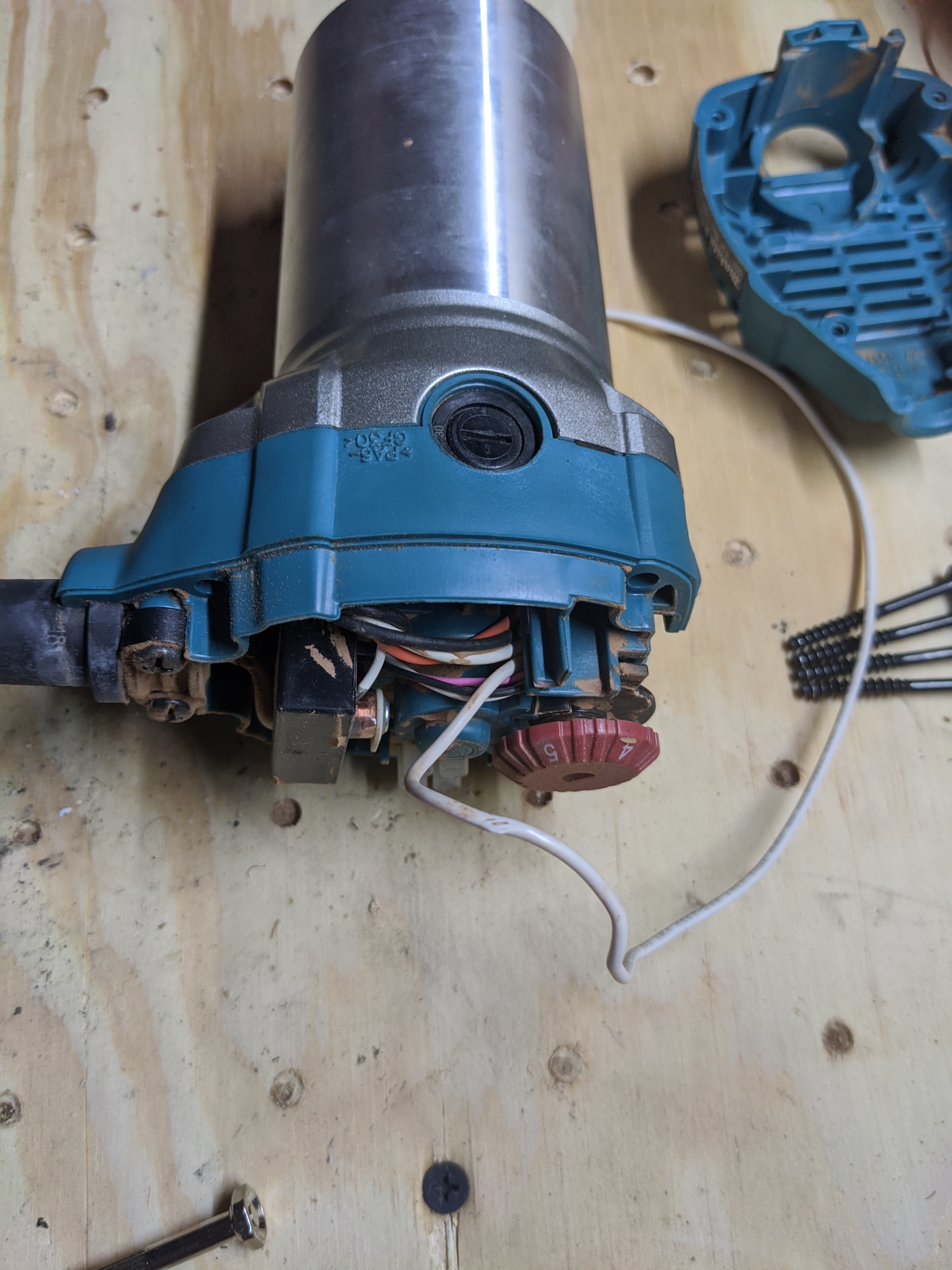
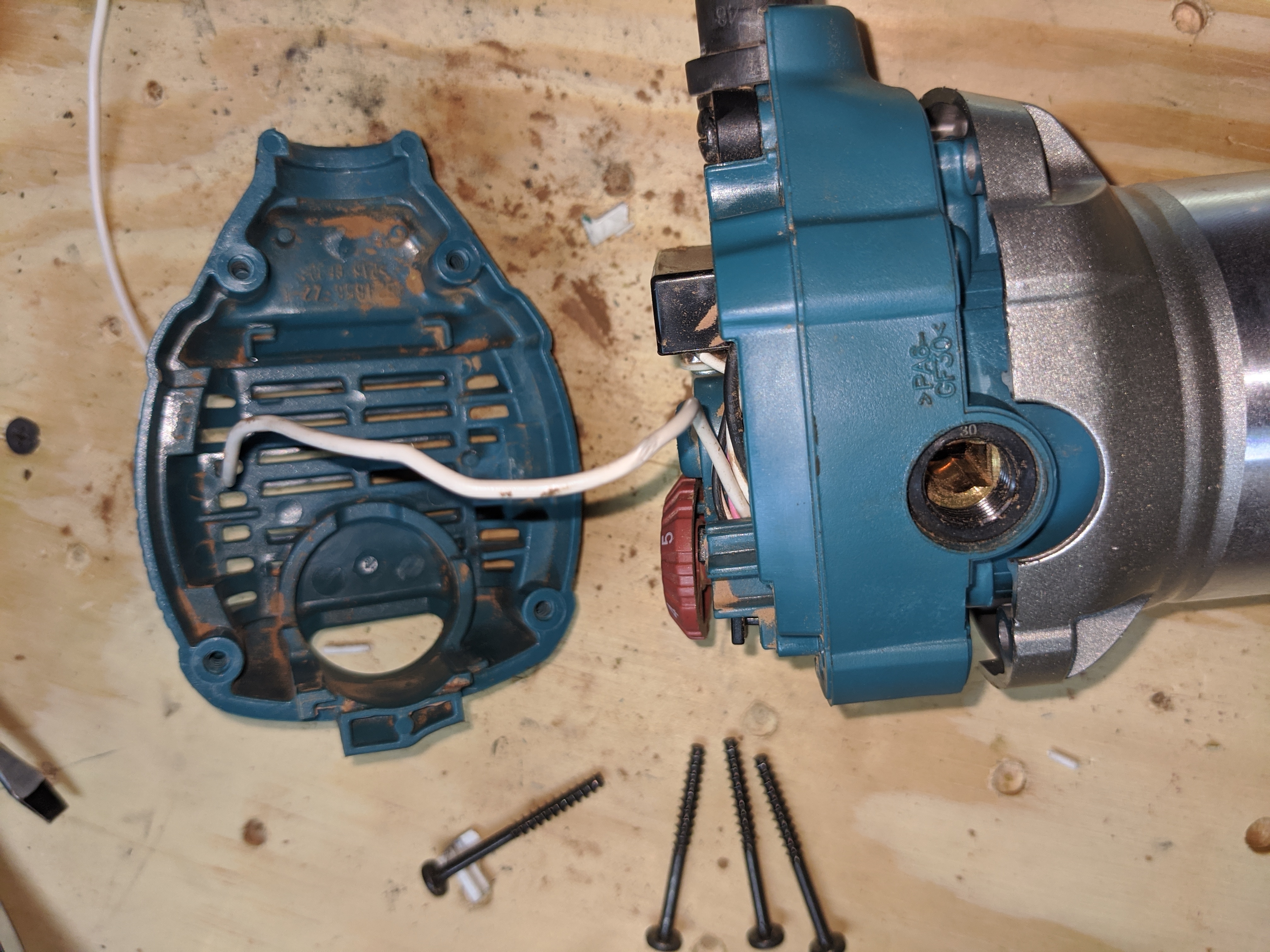
Here’s a pic of mine almost together. You can see where my warning comes from. I broke the housings for the brushes by being a brute.

Keep going

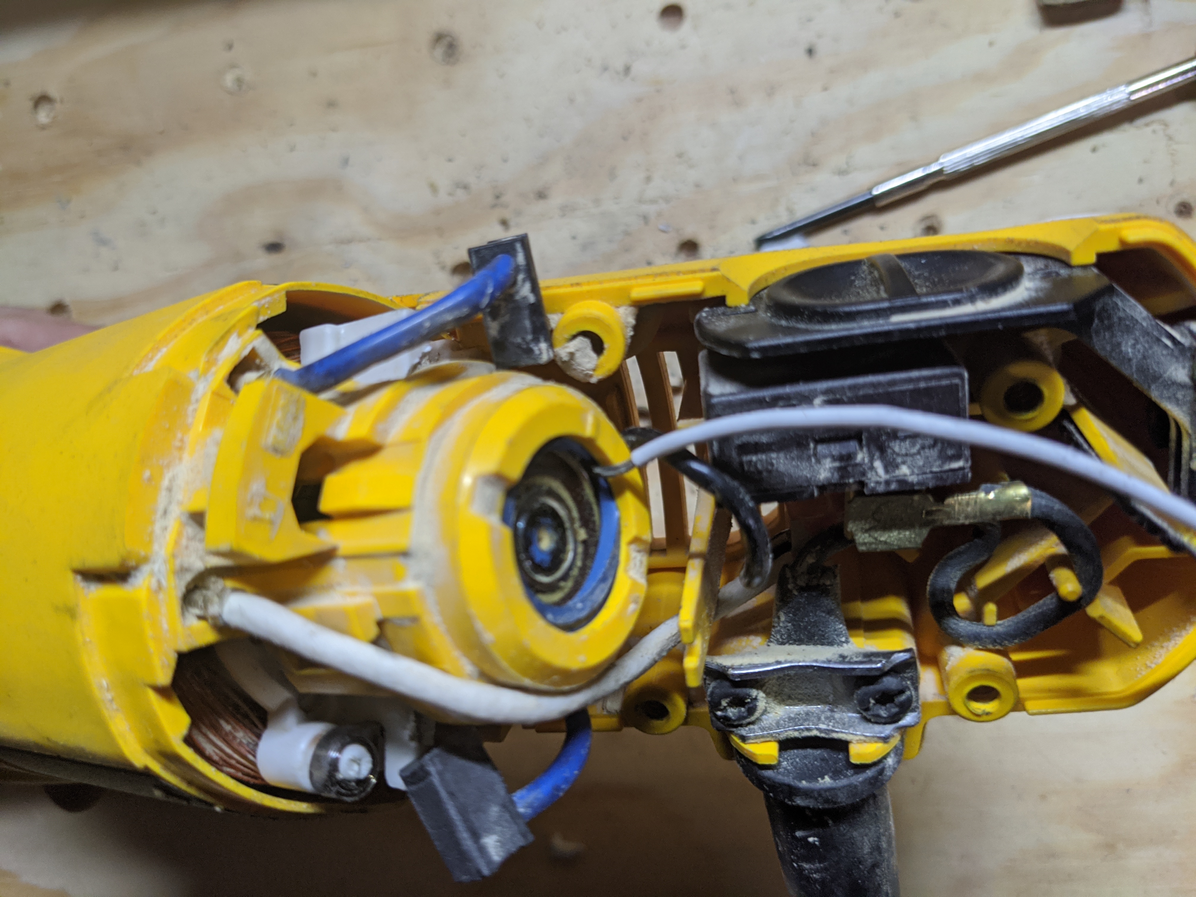
At this point the wire is wedged a bit, but there still isn’t a great deal of force holding it in. Try to get it in this slot so upon reassembly it has a bit more holding it steady. It probably wouldn’t be a bad idea to dab some hot glue or something on there. Or after reassembly, doing so where it comes out of a vent. I suspect it wouldn’t take much to pull this loose and that happening while its running could be fairly interesting.

I fed the wire out one of the vent holes. That is what will run to one of your Z probe pins. The other pin will go to whatever plate you’re using.

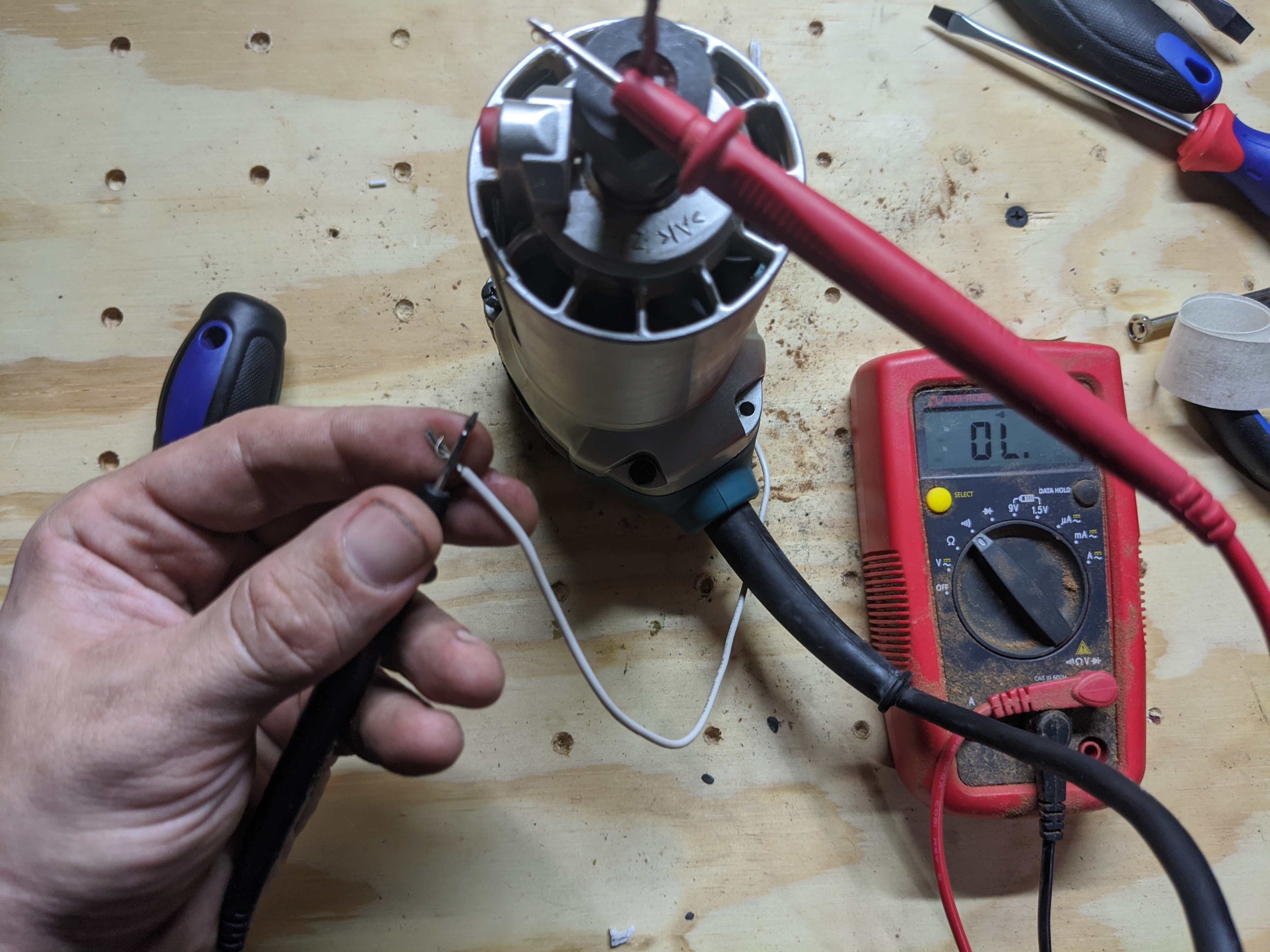
I tested continuity and function of the dw660 and everything seemed ok (even after breaking the housing for the brushes) so I’m pretty confident this will work fine. Get everything back together and go!

2 Likes

Makita RT0701C

K I took mine back apart to get this one documented. You’ll see that my wire is already there, just pretend it isn’t. I also have to eat my words a bit. I kept saying the makita was easier. You do have to pull its rotor out too. Still easy though. I just spent five minutes taking these pictures and taking it apart and putting it back together again. Took me longer to type this post up than to do it.

Those with good eye sight might notice my wire has some nicks in it and some browning. When I first tried this I just grabbed some random piece of old wire I had laying around, it wasn’t damaged from use. It started out that way lol. I guess I should replace it.

Behold, the makita. Definitely my favorite mpcnc router.

You’ll need to remove four phillips screws to begin disassembly. You can see two of them in this picture.

The top cover comes right off to expose some of the goods.

In the above picture you can see my white wire is already there. Pretend it isn’t, or use it as a reference if you need. Next you’re going to have to gently start prying things apart. It shouldn’t take too much force, but it is a decent distance you have to pry it. That bearing is press fit in to whats left of the upper body.

If you look closely you can spot a gap that makes the prying easy to get started.

You’ll need to remove the brushes too. It’d probably make sense to do this earlier but I forgot about the darn things again. Doesn’t harm the disassembly to do it whenever but you’ll need them out of the way before you can put it back together. You can’t reach them like you can the dw660.


j

You should be looking something like this so far (Ryan I hope your forum likes lots of pictures)

Whats coming might have some room for creative freedom, but I’m going to show you the path I chose for the wire. If you lift up the rotary dial thingy, there’s a hole kind of underneath it you can shove your wire through. It’s the white wire resting on my finger.

You might be able to push it through or you might need some needle nose pliers to reach in there and grab it. Pull it through and out enough that you can bend the tip like in the next picture.

Now you want to pull it back in and twist/turn it until you get the wire against the wall and pointing down as well as you can. It was hard to get a picture of. just think of what the wire will want to do when you force the bearing back in. We’re giving it encouragement/a head start.

Time to start putting things back together! Very carefully start sliding the rotor in, while you have a hand on everything else in a way that makes you confident the wire is going to stay where you put it. You’ll feel resistance when the bearing reaches its home. Push it in a little. At least enough that it has grabbed the wire and its holding it in. You don’t need to force it in all of the way. Let the screws do that for you later.

Path the wire so it goes under the rotary and through the slot that holds a couple other wires. Then run it out of a vent hole.


Place the top cover on and start tightening the screws. I chose two at a diagonal and I went back and forth letting the screws force the pieces the rest of the way together. Then I did the last two.

Get your brushes back in

You should be done! Test continuity and go make all of the chips

5 Likes

reserved for faq maybe, and how I handle my plates

short version until i get pics/finish my rebuild

I have an aluminum corner bracket on my 0,0 corner. It is wired to the other pin for the z probe. Any conductive object secured to it acts as its own touch plate (0 offset). It’s also split off to two different touch plates. The “puck” style and the one Ryan sells in his shop. Both have their uses for various things. The puck has heft and you can just plop it on whatever and go hands free. Sometimes its too tall though and that’s where Ryan’s is superior. But it lacks weight and you have to hold it. If the bit touches any of these things it closes that pin/circuit to act as a probe.

1 Like

I’d be very interested to see the instructions for a Makita! (And hopefully the cheap clone I have will work similarly.)

How reliable is the electrical contact through the bearings and through the end mill? Could there be too much grease in the bearings or could the end mill be too dirty to make proper contact? What’s your experience?

I had the same worries but after using it for several months with zero failures I’m comfortable saying its reliable.

I assume for the bearing to not have consistent metal to metal contact it’d have to be really worn out/wobbly. I can’t claim any special expertise about that though. Just personal “it works for me” experience.

Dirty bits I’m not entirely sure on other than another “its never been a problem for me.” I imagine if its dirty enough it’d just push in to the probe some unnoticeable fraction of a mm until it finds contact.

My machines do mostly aluminum though, that could be relevant

Edited to add two more things: I tried it once with the router turned on out of curiosity. This causes false triggers and did not work at all.

I should have the makita pics up tonight. It was hard to talk myself in to taking them apart on functioning machines but since one is idle right now for the upgrade its the perfect opportunity to get it done. It was even easier from what I remember

I don’t have any problem I have a clip on the project but as long as the router is plugged into the same circuit I don’t need the clip on the router or mill it is grounded and completes the contact. Found this out by accident reached over to unclip and it was not hooked up you can even do it with the router on if you have the nerve I first checked it out with foam to be sure it was not a fluke but it works everytime as long as router is plugged in

I could swear I tried that and it didn’t work for me. I’m going to probe it again tonight and verify though.

1 Like

Be careful plugged into same circuit and controller use foam to test. I use GRBL but dont see how firmware can make a difference

Thanks for sharing your experience. It definitely makes me more comfortable trying it out!

No need to take apart anything just for me though. I think the general idea is clear enough for me to try it myself without any more specific instructions.

Your way will work know matter what so no mistakes

1 Like

For a quick text description on the makita if you rip in to it before I get pics up, all I remember taking off was the top cover. The upper most bearing was press fit and accessible from there then it was the same process. Hold stripped wire on the wall, shove bearing back in to wedge it, run wire out of one of the vents and reassemble.

Also no worries, its something I get asked about a lot elsewhere and have been meaning to do for a while. I just wanted to run it for a while before I did. Plus I’m lazy.

1 Like

I have not seen such good teardown and assembly of a 660 before that is impressive :exploding_head:

1 Like

K the makita pictures/instructions are there now. Hope it helps!

OMG that is how a how to is suppose to be given!!

1 Like

For anyone that has done this, did you have any issues with continuity? I have mine apart right now and I am not able to get consistent continuity between the top bearing and the arbor shaft at the end (where the bit goes). It’s really odd. I am positive that the probes are making solid contact on both ends. Is there a coating on the bearing outer race and arbor shaft that needs to be removed? I have cleaned both parts with lacquer thinner, so there is no oil present… One difference I notice with the pictures in this post and my new Makita RT0701C is, at the top where the top bearing seats, in the post it looks as if it is metal… in mine, it’s plastic…

I’m extremely late to seeing this, apologies for that. Did you figure this out? Did you happen to take any pics?

“It just worked” for the 3 I’ve done this to but maybe there is an internal difference on newer ones. I think my newest makita was bought a year+ ago

I was not able to figure it out. It seems there is no continuity between the outer and inner race of the bearing at the top. Just like the collet is coated so it prevents continuity too. I think everything is against it, so I just put it back together and continue to use a touch plate and clip to the bit.