Sorry if someone asked this before, I couldn’t find anything. I’m printing a case to house the RAMBo 1.4 and a Raspberry Pi 3 so I can use Octoprint to control it. Is been working fine using the USB but since I wanna house them I thought it would be nice to connect like I do with my Prusa 3D printer, using the GPIO pins directly. I couldn’t find any guide. Did anybody get this done? Is it even possible with the RAMBo 1.4?
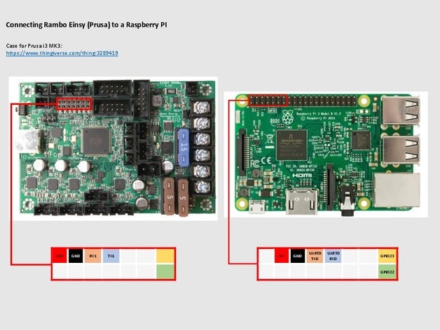
All you need to do is connect the RX and TX pins. BUT You’ll need to figure out what voltage the RAMBo rx/tx pins are running at. You’ll probably need to step the RAMBo pins down to 3.3v for the rpi. I’ve used these in the past for connecting arduinos to rpis: https://www.sparkfun.com/products/12009 If you don’t step the voltage down you’ll fry something.
RX/TX1 isn’t enabled by default. The USB is on rx/tx0, I think… Now I have to check it.
I don’t worry too much about 5V/3.3V with UART. The 3.3V from the pi to the rambo is fine, it will be enough to register correctly. The 5V tx from the rambo to the 3.3V rx on the pi might hurt it. If you were worried that sparkfun board will work, but I think just a resistor would also be enough to dampen it enough to save any trouble. Worst case, you have ruined the pi. But I think there’s <10% chance of that. It’s just a guess though.
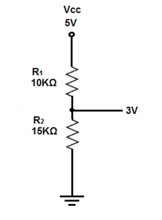
That would probably work. The rpi operates at 3.3v so in a perfect world your R2:R1 ratio would be 2:1 to get 3.3v from 5, so if R1=10k then R2=20K.
You only need to do this from the RAMBo’s TX pin that’s connected to the rpi’s RX pin. @jeffeb3 suggested above that you should not need to step up the rpi’s TX to 5v for the RAMBo. X39’s ground pin should be fine.
[EDIT]
To clarify, in your schematic instead of Vcc 5v you would connect to RAMBo’s TX pin (5v), and the 3v output goes to rpi’s RX pin. The RAMBo’s RX pin can be connected directly to the rpi’s TX pin
That will work. But I also think just the 10kOhm between them will work too. The resistor to ground is fine, but just limiting the current with the first 10kOhm resistor is enough to keep it from breaking. I remember seeing that a lot when connecting a 5V uart to esp8266s, which are very sensitive and are 3.3V.
Now, connecting the RPi TX on the Rambo RX0 and the RPi RX with the 10k Ohm on the TX0 did the trick.
I’ll leave it connected overnight hopping to see my Pi not fried in the morning.
Thank you!
Thanks turbinbjorn. I bought a few buck-converters for attempting to do this with my ender 3. There are plenty of videos on this, but it uses the meanwell power supply.
I guess I’m just afraid to fry the RAMBO… given the the price tag & my non-existent EE knowledge.
Maybe I’ll try on my creality board first to get comfortable with the mechanics and then try it later on the Rambo.
Understood. I think I’m confusing a few things here.
I’m going to table this for now, because I just realized I would need a beefier power supply (I have the Kaster recommended by Ryan) and running off the Rambo isn’t realistic.
Thanks guys for walking through this with me and sorry to hijack the thread.
I’ll let y’all get back to the real messages of this thread
Here’s how I suggest thinking about it. The RAMBO is a power consumer (and to some extent a distributor), not a power provider so I wouldn’t suggest trying to use it to power anything beyond the fans and other components for which it has connectors. The Rambo sits “downstream” of a power supply, and this power supply sits downstream of a switch. Split the line coming in to the Rambo to create a separate power line and put the buck converter on the newly created power leg and tune it to provide the proper voltage for the Raspberry Pi. Then the main switch can turn both on and off.
Conventional wisdom says you need to be careful to use the OS command to shut down the Rasberry Pi before turning off the power. Just “pulling the plug” can result in a scrambled file system which could prevent the Pi from booting the next time. If this happens, then you need to re-image the file system’s micro SD card.
There are online guides for putting a switch between a couple of the gpio pins to act as a shutdown button with appropriate OS config commands to turn it into a shutdown or reset button. Octoprint supports plug-ins for controlling power to the printer via relays as well. Fancier setups use the Pi to control one power relay to the printer, and a second a relay to in turn control the power to the Pi. In this way, pushing the button when things are powered down will power them up, but pushing the same button when things are powered up triggers an OS shutdown followed by the second relay removing power from the Pi.