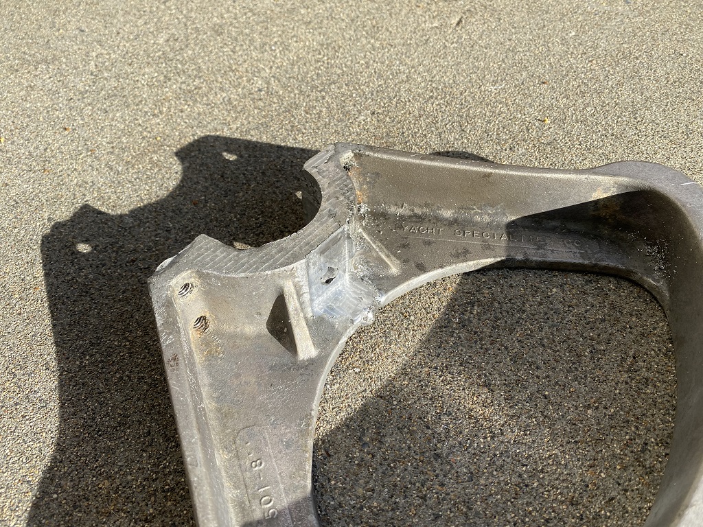
My buddy bought an old sailboat that needed some repairs, and one of the items included the steering quad (it’s similar to a bellcrank on an airplane). The original had oxidized away and broke in several places due to a leaking hatch above it. The rear clamp part was broken beyond repair and needed, and the main pulley part was cracked and corroded very badly where it meets the rudder shaft. For my buddy, buying a replacement was not practical given his budget and time constraints. So I offered to help him with my Primo.
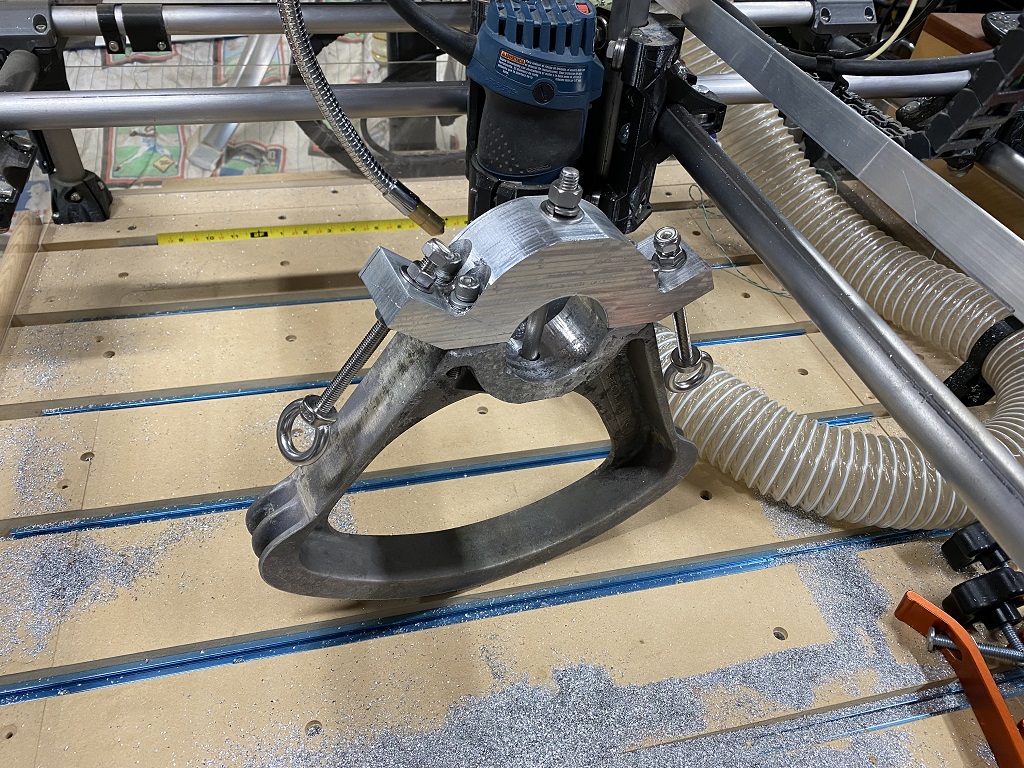
He first brought the pulley part to another friend who was able to TIG weld it back into something useable. The part had a 3/8" spread crack at the hub, and about 3/4" of material corroded on the corner of it’s clamping surface. All of that had to be filled in with TIG. Then after beltsanding the back of the pulley part to be able to clamp it, I put it on my Primo… and started literally 2x 12hr days of cad/cam/cutting. With some luck helping us along, he now has a working part that is perhaps much stronger than the original Al casted unit.
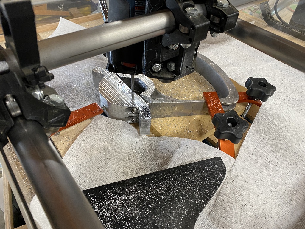
If you like DIY cnc, you’ll love that improvised clamp to the left. It’s a long 5/16 bolt that goes ~1/4" into a blind hole on the part, held up with 2 chunks of 1/2" ply, and pushed down with a standard t-track clamp. It worked perfect for holding that half flat for the boring and facing operations:
Those chips are about 1.5" deep in some areas here:
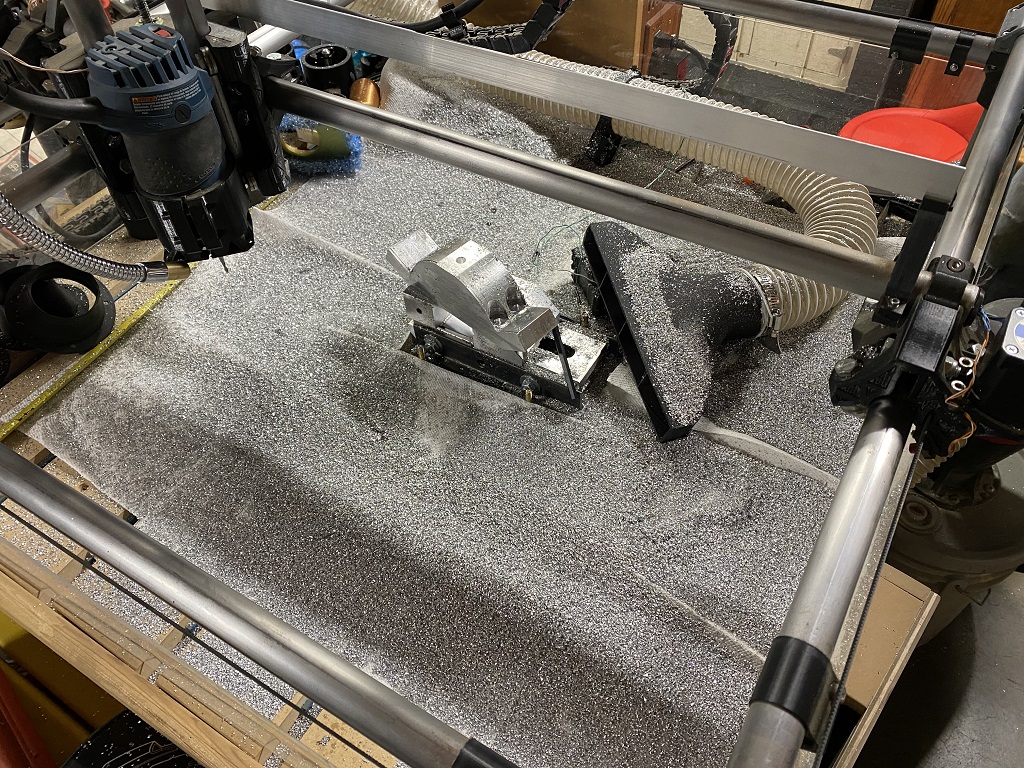
That’s just the chips that were on the paper towels, but there’s a lot more on the ground and in the vacuum bucket:

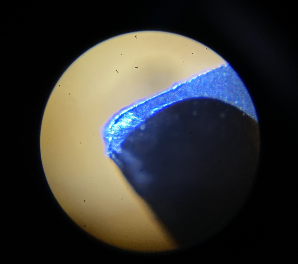
This is what the Spetool 1/4" 2-flute Alum upcut that did most of the work looked like afterwards (yeah it’s done dizzle):
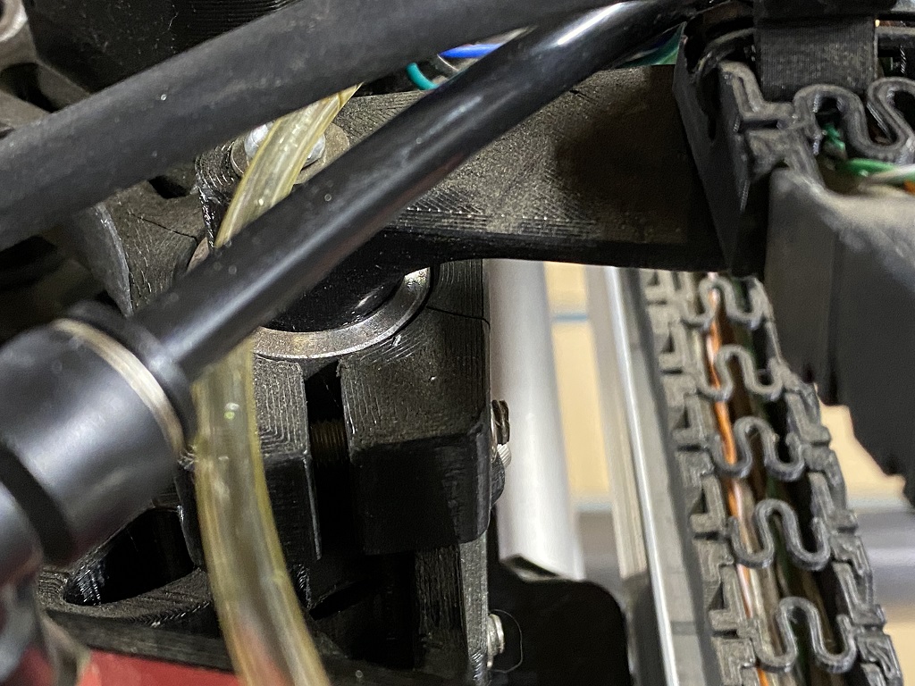
I learned that a primo will cut aluminum even with a broken motor mount:
What luck, you may ask? Well, besides this being a job of epic proportions for a Primo and a Bosch Colt router with Chinese carbide, we did have a few mishaps as well. My buddy was trying to be helpful by sweeping chips off my controller box, and accidentally hit the e-stop with the brush, LOL!
This happened while the an operation was 1.5" deep into slotting the main clamp part off of the 2x3x12" block of Al stock. It lost position ~6hrs into the main slotting operation. I managed to recover the part, flipping it on the vise, and sneaking into it from behind with an offset. This resulted in that ~1/8" wide step that protrudes out about -.020" on the profile of the clamp part. It was of no consequence for the application. My buddy just sanded off the step on the clamping surface to give clearance.
It also required a mix of skill and luck to get the bore lined up correctly. The approached we used was making several gcode files to “walk in” on the bore size… starting with 0.1" radius undersize, then 0.050, then 0.010, then finish pass. This way we could tweak the x/y position between cuts to get it as close to kissing the original bore as possible. This went perfectly, and pretty much all the filled in weld material was touched in the clamping surface, leaving a full and smooth cylinder that will hold well on the stainless rudder shaft.
The last part of luck involved, was that we made it through with just one cheapo endmill, and with a broken Z motor mount!!! Of course we used flood/mist, and have feedrates more or less dialed in. I didn’t notice until after it was all done, but I believe the z-mount cracked toward the end while facing that weld on the back side… dropping off welds as it cut was a bit rough, and after that the cuts made a lot of bad noises. At that point though, it was just a surface to seat a washer, so we let it finish the job.
Note the visible chip welding on the deep slots was caused mainly by inadequate chip evac. Once the mill was deep enough where the unfluted shaft was against the slot wall, depending on the direction of cut, the air would push some chips back and they would wedge in between, welding to the mill, which made all those galling marks. They were just aesthetic though… the surfaces were all plenty smooth for the application.
It was certainly an epic job for any DIY cnc… but I think it speaks to the robust design of the Primo, and perhaps the Colt router as well. Oh, and I guess Ryan can put “yacht repairs” on the list of things his machine can do lol!