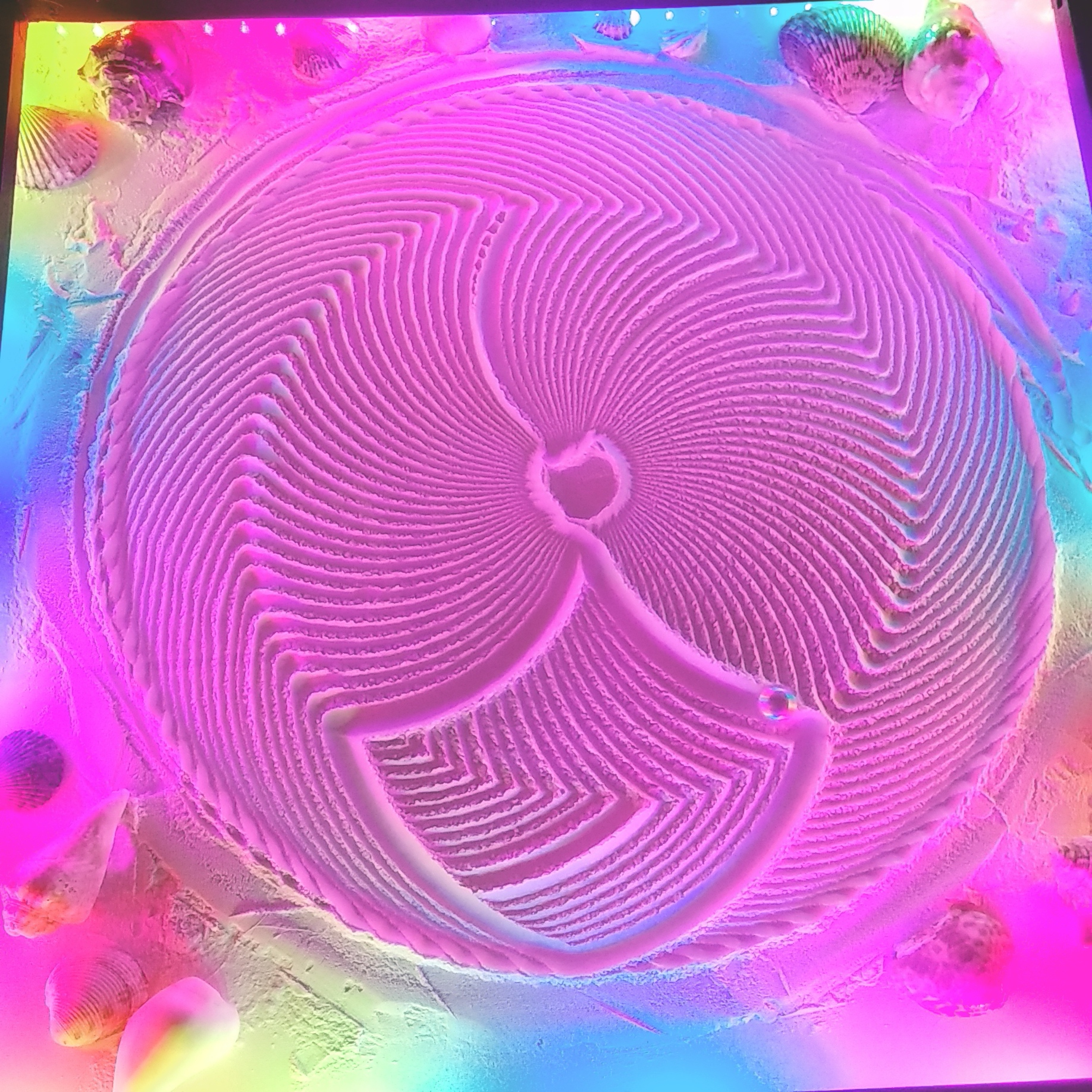
The baking soda is very white and works ok, but the critter powder is a bit more gray and I think the patterns stand out better. I did a 50/50 mix but I will try other mixtures.
1 Like
Cool idea with the “ash” thingy. I’ll be on the lookout for that 
1 Like
Hi @jchaplain123, awesome work on your sandtable!
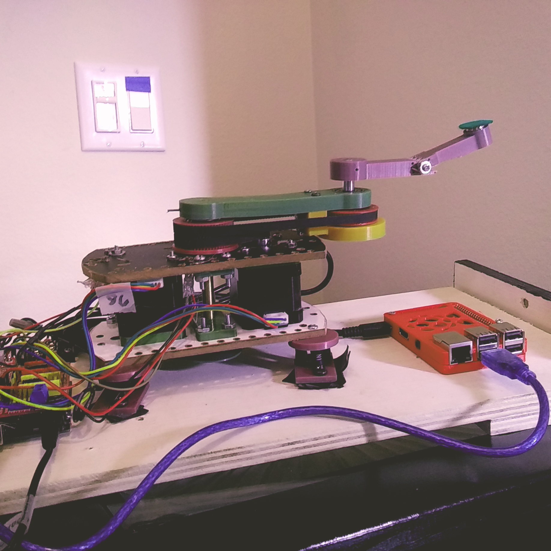
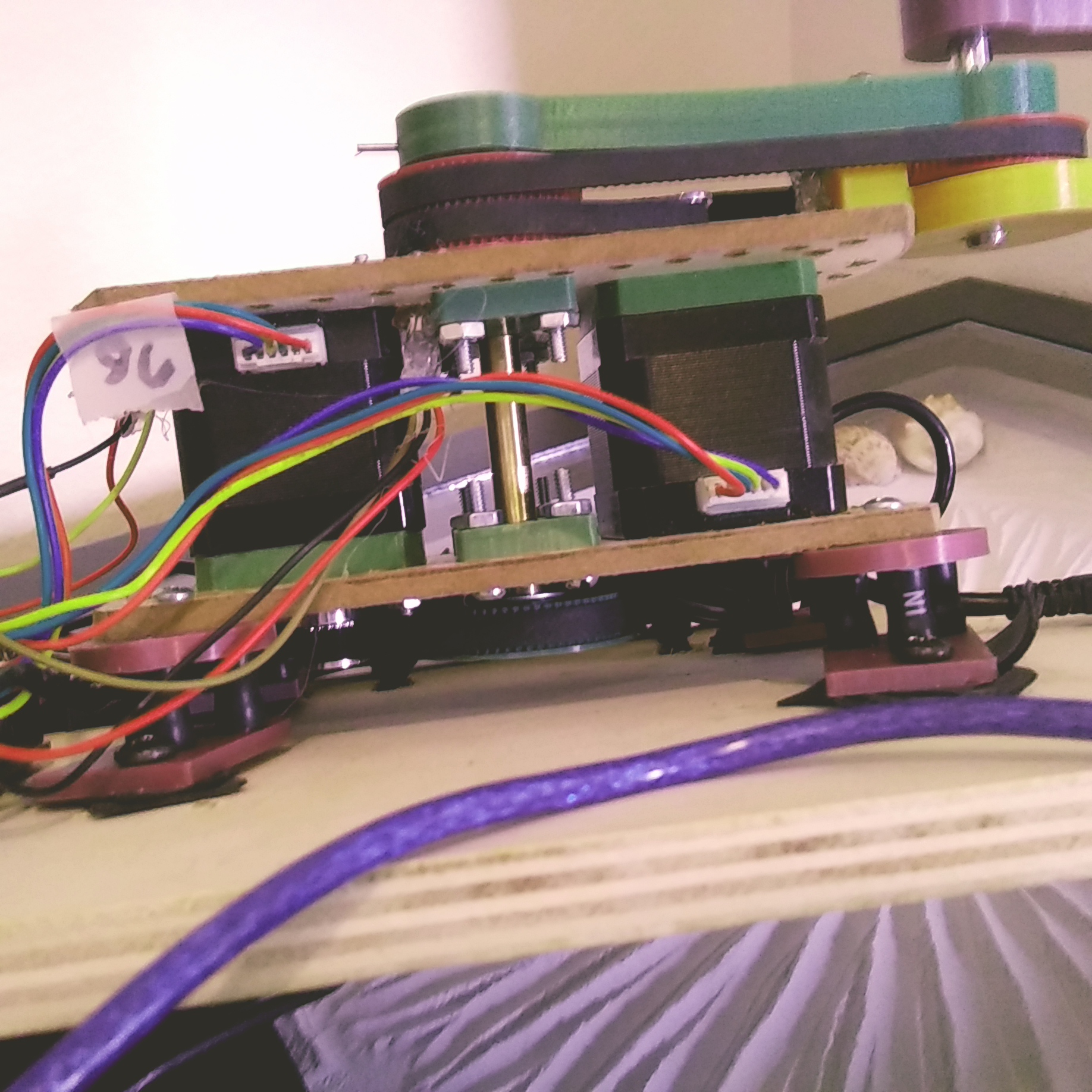
It looks like you’re using a raspi + arduino + ramps + steppers? Cool combo.
If you ask for suggestions, the most valuable one I can give is probably this: Check out sandify.org  But if you’ve been reading this forum, I’m sure you’ll already know.
If you’re starting from scratch regarding the code on the raspi, it might be worth checking out the github repo a friend and I started for this: GitHub - ratnaweera/sandtrails: Tracing sand on a polar plotter . You’re more than welcome to use it and contribute.
Out of curiosity: Any specific reason the table is square shaped? (The work envelope of your SCARA axes would be a circle…)
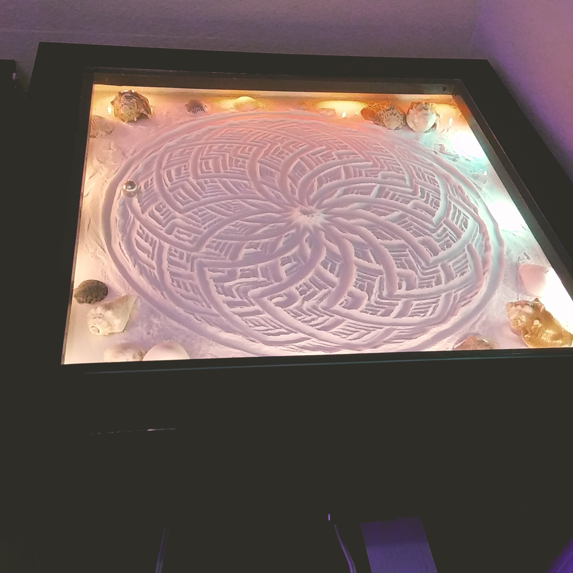
Thanks for the feedback and that’s a really nice build you made! I like the round table. The reason I have a square table is that I was originally going to build a Zen xy table. I actually did build the Zenxy but just before I completed it I decided it was probably going to be far too noisy and not a very elegant solution. Then I found this web page with a Scara bot? design. ( again having problems posting links here so its alwaystinkering dot com/2020/01/14/diy-kinetic-sand-art-table/ I decided to continue with the square table I had made because I wasn’t even sure this would work but it works VERY well and is pretty quiet if you set it up right. Now, the biggest problem I’m looking at is programming. I have been making designs from Sandify but they don’t come out anywhere near the intended design on my machine. On your design the Y axis is always swinging about a central fixed point. On my design the y axis swings from the end point of the xaxis arm so the programming is very different ( I think.) I need to go back on the website a mentioned above and see what his solutions were. I have been writing my own visual basic solution but maybe there is a better way. I think I am going to like having a square table as it will allow me space to decorate the corners with sea shells and such and also it will have a hinged on the back swing open top so that I can level the bed easily. If I make another I will probably go with the round IKEA table. I am using a Raspberry pi 3 B+ with an Arduino UNO and Arduino CNC shield. I love that I can use NOMACHINE software to remotely control the raspberry pi. ( I assume everyone is doing that? It’s so convenient!) On the raspberry pi I’m running bCNC software to run the gcode.
Roman’s solution is to use python on the pi to control the steppers, which gives easy access to rewrite the kinematics. I would think long straight lines would end up curved if you were just translating the endpoints from cartesian into scara, without accounting for the steps along the line. Running all of that on the pi, and just using the CNC shield to interface with the drivers might work well for you, and you can start with Roman’s codebase, which I think uses .thr files as input, which would also make the kinematics a tad easier.
I don’t use NOMACHINE, I just use ssh. I don’t run a desktop on my pi’s, usually. I just run code from the command line. But I have been a linux user since at least 15 years.
Thanks for the info. I’ve started writing a VB program that can take xy gcode and inverse kinematic convert it to arm angles for my scara. All of the factors involved is what has given me pause and take time to hunt for an already proven and documented programming solution. Factors such as arm lengths, arm spin directions, arm revolutions per stepper program distance, straight line moves by adjusting axis feedrates, etc, etc. I was a cnc programmer for many years programming multi-axis machines so I’m surprised that this solution seems so difficult. I would have thought that maybe someone had made a cad system postprocessor for this already. I will post any progress I make. Thanks again.
If you want me to take a look at the math, I can. Or you could try to do some simple shapes, like a single rectangle, and show what you expect it to be and what it is. I can imagine a few pitfalls when trying to do this. One of which is that a line segment in cartesian ends up being an arc in scara, so you’ll probably have to create intermediate points along the line in cartesian, and then convert each point into scara angles.
I can even look at the visual basic code, although I’ll be honest, I’ve looked at some before and it made my head spin.
Thanks for the offer to help. I did figure out the math enough to be able to convert xy points to angles for arm1 and arm2, ( at least in the first quadrant, ) but the questions are sublime and I guess I better start going into test mode. Example…where are the arms at machine zero? Do arm1 and arm2 lie folded back on each other on the + or - x axis or on the + or - yaxis? Does it matter? Should the choice be made based on the next ( first or second) goto point? I also agree about straight line moves will likely all be arcs so I may need an algorithm to break out the straight line into a series of intermediate goto points. I think a circle could face the same requirement to actually come out circular? No clue at this point really. I began writing a test input program and running it this week but it just does strange things. Will try nailing down very basic moves over the next week and go from there.
Several of these issued are solved in sandify if you start with the theta rho as input. I’m sorry for not suggesting it earlier. Sandify outputs an angle and a distance from the center. I also have to make tiny movements, so a single square ends up being a few hundred vertices. It also helps you as you get close to zero, because it always defines an angle.
The math might be a lot easier too. The first arm is the only one that changes with theta, and the second arm is closely related to radius, but both arms need a little adjustment based on the radius.

I got into it more and realized that in the VB program I wrote that turns xy values into angle1, angle2 values I wasn’t adding the arm1 angle into my arm2 angle calculations so it was doing crazy things. After sorting that ( and a few other things out) I can now start making some fun patterns. Got a new string of ws812b rgbs to light things up as well. On the programming…I get divide by zero errors at times compiling but I’m sure I can get back into solving that but I think I’ll come up for air for a few hours at least before diving back in!
4 Likes
Funny, im sure I left a reply in this thread…
Anyway, would it help applying a coat of Plastidip on the inside of the tubes?
To deaden the sound? Not sure.
Still struggling with converting xy co-ordinates to arm angles. Your suggestion to use theta rho as input won’t help much ( if I understand correctly what you are suggesting.) The Sisyphus sand table arm action is very different that the scara arm in that the rho is rotational about the end point of the base arm rather than simple 2 directional travel along the arm which would be MUCH easier to deal with. I knew this going in but I thought I could solve it with some programming. I can feed xy points into my VB program and output the proper angles in the 1st quadrant, but after that it begins to get very confusing. I just thought I would update my project status. I haven’t even begun to consider forcing this arm to draw straight lines yet. 
No need to struggle on your own. I have a lot of programming, math, and path planning experience. I have enough experience to know it is hard, and it is harder working inside your own head. Unlike most of the topics I help with here, this is actually an area where I am an expert. Let me see where you’re at and I can try to help.
Or, if you give me some more details on how the mechanism works, I could try to code up some simple examples/tests that would help you gain some ground.
Is it true that the green arm is controlled only by one motor, and the other arm is affected by both motors?
I will update you later today or tomorrow. Thanks!
The way this 2 axis scara works is that arm1 and arm 2 are both 100mm long. Arm1 ( the green one) rotates about the center and arm2 ( the red one) rotates about the end of arm1 independently. For example, if I rotate arm2 to 45 degrees relative to the machine x axis, then I rotate arm1 to any angle, arm2 angle stays at 45 degrees relative to the machine x axis. It’s a cool design that both arms rotate individually and the rotation angle of the second axis is not dependant on the rotation angle of the first. But of course the location of the endpoint of arm2 changes as arm1 rotates.
In my attempt to create patterns I wrote a VB program ( could use any language,) that reads xy values by stripping the values out of a sandify ( or other) gcode file, converts them to arm1 angle and arm2 angle and writes out a new gcode file to run on the machine. This new gcode file rotates to the proper arm angles. Example: G01x150y35 calculates that arm1 angle should go to 26.4989 degrees and that arm2 angle should go to 52.767 degrees.
This verifies correctly in my cad system, as long as I am working in the first quadrant.
Now, sending a value of G01 X6.0 will rotate arm1 360 degrees. ( Same with arm2 with G01 Y6.0 will rotate arm2 360 degrees.) Based upon this 1 degree of rotation for either axis is .016666. So, if I send the command G01X-0.441647704579837 Y 0.879446696923409 I get to the arm1 26.49 degrees and arm2 52.767 degrees placing the magnet at the correct x150 y35 location.
To sum up open issues…
- My working circle is 400mm dia. Not sure if I should consider x0y0 ( center of circle) to be program zero or x200 y0 to be program zero, or if it will matter as I get deeper into this.
2)I’m not sure if I should change my stepper motor values so that one rotation is some other value than 6.0. I don’t think it matters as long as I know what the value is and use it correctly in my calculations.
I have both arms turning cclw with a positive value. I think this is also just a convention to be aware of while programming and not important.
-
Every position will have two solutions for arm1 and arm2 angle. I don’t know when or if I am going to care to control that.
-
all motions between 2 points are going to be arcs due to the mechanics of the machine, so to generate (draw) a semi straight line, large moves will have to be broken down into smaller line segments. This should be fairly easy programmatically but I think it is ( perhaps?) going to be joined with the issue of choosing which of the 2 solutions of arm angles to use. It may be a secondary consideration though.
-
I think the issue of solving getting correct arm angles for values in all 4 quadrants is the number one priority and after that work out the other issues.
Final thoughts… Possibly this wheel has been invented before? So I have done a bit of searching on inverse kinematics and someone said that using “fuzzy logic?” is a good method. Someone else said that building a huge array lookup table is a good method. Another thing I was looking up is Matlab but that looks pricey and this is a random hobby for me so spending out for software is probably something I’m not going to consider to make fancier sand patterns and working through this sort of thing is half the fun of it anyway! Please let me know if you need more clarification or information of any kind. I can clean up and send you the VB program I have so far if that helps. I think I will post it just in case you can make anything of my thought process from it.
'Here is the Visual Basic program I have written so far;
’ It probably has some junk in it for testing purposes.
Imports System.Math
Module Module1
Sub Main()

    FileOpen(1, "g:\t1.gcode", OpenMode.Input)
    FileOpen(2, "g:\t1.ngc", OpenMode.Output)
    Print(2, ("$HX"))

    Print(2, vbCrLf)
    Print(2, ("$HY"))

    Print(2, vbCrLf)
    Print(2, ("G01X0.00 Y0.00 F50"))

    Print(2, vbCrLf)
    Dim xval As Decimal
    Dim yval As Decimal

    Dim angle1 As Decimal
    Dim angle2 As Decimal
    Dim armlength As Decimal = 100

    Dim arm1_angle As Decimal
    Dim arm2_angle As Decimal
    Dim a4 As Decimal
    Dim angle4 As Decimal
    Dim half_dist As Decimal
    Dim dist As Decimal
    Dim yxval As Single
    Dim xtxt As String
    Dim ytxt As String


    '  Dim tval As String
    '  Dim Endx As Integer
    Dim line As String
    Dim test As Decimal
    Dim test2 As Decimal
    Dim nval As Integer = 1

    While Not EOF(1)


        line = LineInput(1) 'start getting data lines


        Dim SearchWithinThis As String = (line)
        Dim SearchForx As String = "X"
        Dim FirstxCharacter As Integer = SearchWithinThis.IndexOf(SearchForx)
        ' Dim Nvalx As Integer = (FirstxCharacter)

        Dim SearchForY As String = "Y"
        Dim FirstyCharacter As Integer = SearchWithinThis.IndexOf(SearchForY)

        Dim side1 As Decimal 'right is 0 left is 1 used to mark quadrant 1 and 4 or 2 and 3
        Dim updown As Decimal 'top is 0 bottom is 1 used to mark quadrant 1 and 2 or 3 and 4
        Dim quadrant As Decimal
        xtxt = Mid(SearchWithinThis, 5, 11)

        Dim Xtxtdec As Decimal = Val(xtxt)
        If Xtxtdec >= 0 Then
            side1 = 0 'quadrant 1 or 4
        Else
            side1 = 1  'quadrant 2 or 3
        End If


        '   Print(2, "The y ppoint value is ")
        ytxt = Mid(SearchWithinThis, (FirstyCharacter + 2), (FirstyCharacter + 6))
        Dim Ytxtdec As Decimal = Val(ytxt)

        If Ytxtdec >= 0 Then
            updown = 1 'quadrant 1 or 2
        Else
            updown = 0  'quadrant 3 or 4
        End If

        If side1 = 0 And updown = 1 Then
            quadrant = 1
        ElseIf side1 = 1 And updown = 1 Then
            quadrant = 2
        ElseIf side1 = 0 And updown = 0 Then
            quadrant = 4
        ElseIf side1 = 1 And updown = 0 Then
            quadrant = 3
        End If
        Print(2, "the quadrant is ")
        Print(2, quadrant)
        Print(2, vbCrLf)
        '------------------------------------------------------

        '------
        'calculate dist using sqaroot of (xval squared) + ( yval squared)
        dist = Math.Sqrt((Xtxtdec * Xtxtdec) + (Ytxtdec * Ytxtdec))
        half_dist = (dist * 0.5)

        Dim dd As Decimal
        Dim de As Decimal
        Dim a1 As Decimal
        Dim a2 As Decimal
        '            Dim xval As Decimal = Xtxtdec
        '           Dim yval As Decimal = Ytxtdec

        If Ytxtdec = 0 Then
            Ytxtdec = 0.001
        End If
        dd = (Math.Atan(Xtxtdec / Ytxtdec))
        a1 = (dd * 180 / PI)
        'Print(2, "the first angle A1 is")
        'Print(2, a1)
        'Print(2, vbCrLf)

        '

        '------------------------------------------

        dd = (Math.Acos(half_dist / armlength))
        a2 = (dd * 180 / PI)


        '--------------------------------------------------------
        'calculate arm 1 angle (from x axis) subtracting angle1 and angle2 from 90 degrees

        Print(2, "Arm 1 angle from x axis is ")
        If quadrant = 1 Then
            arm1_angle = (90 - (a1 + a2))
        ElseIf quadrant = 2 Then
            arm1_angle = (180 - (a1 + a2))
        ElseIf quadrant = 3 Then
            arm1_angle = (270 - (a1 + a2))
        ElseIf quadrant = 2 Then
            arm1_angle = (360 - (a1 + a2))

        End If


        Print(2, arm1_angle)
        Print(2, vbCrLf)


        '------------------------------------------------------

        '--           'calculate angle 4 value

        a4 = (180 - (2 * a2))
        'Print(2, "Angle 4 is ")
        'Print(2, a4)
        'Print(2, vbCrLf)


        '-------------------------------------------
        'arm2_angle Is 180 minus angle4


        arm2_angle = arm1_angle + (180 - (a4))

        'try adding this in
        Print(2, "Arm 2 angle is ")
        Print(2, arm2_angle)
        Print(2, vbCrLf)
        '   Print(2, vbCrLf)


        '---------------------------------------------
        'Convert arm1 and arm2_angle values to gcode values
        'one rev of x or y is 6mm" ex:G01X6 moves one revolution
        '1 degree move = .0166666mm

        Dim ang_to_mm As Decimal

        Print(2, "G01X")
        xval = arm1_angle * 0.0166666
        Print(2, xval)
        Print(2, "Y")
        yval = arm2_angle * 0.0166666
        Print(2, yval)
        Print(2, vbCrLf)
        'nval = nval + 1
    End While

    FileClose(1)
    FileClose(2)

End Sub
End Module
Ok. This is enough for me to get started. Give me a few days to take a look. It seems like we can get there, for sure.
You don’t need fuzzy logic for this, it is directly solvable.
A lookup table won’t work either, because it will not compensate for when you rotate more than one full rotation.
Matlab is great, but it is really just a programming language and a bunch of tools. You can really do just as much with python and matplotlib. Definitely don’t buy it to solve one math problem.
The steps/unit is somewhat important because Marlin only reads a few characters past the decimal. So you don’t want X0.0001 to be too much different than X0.0002. There are also acceleration and max speeds to consider.
I’m excited to work this out. I have a solution I think will work, but I’d like to try it a bit first.