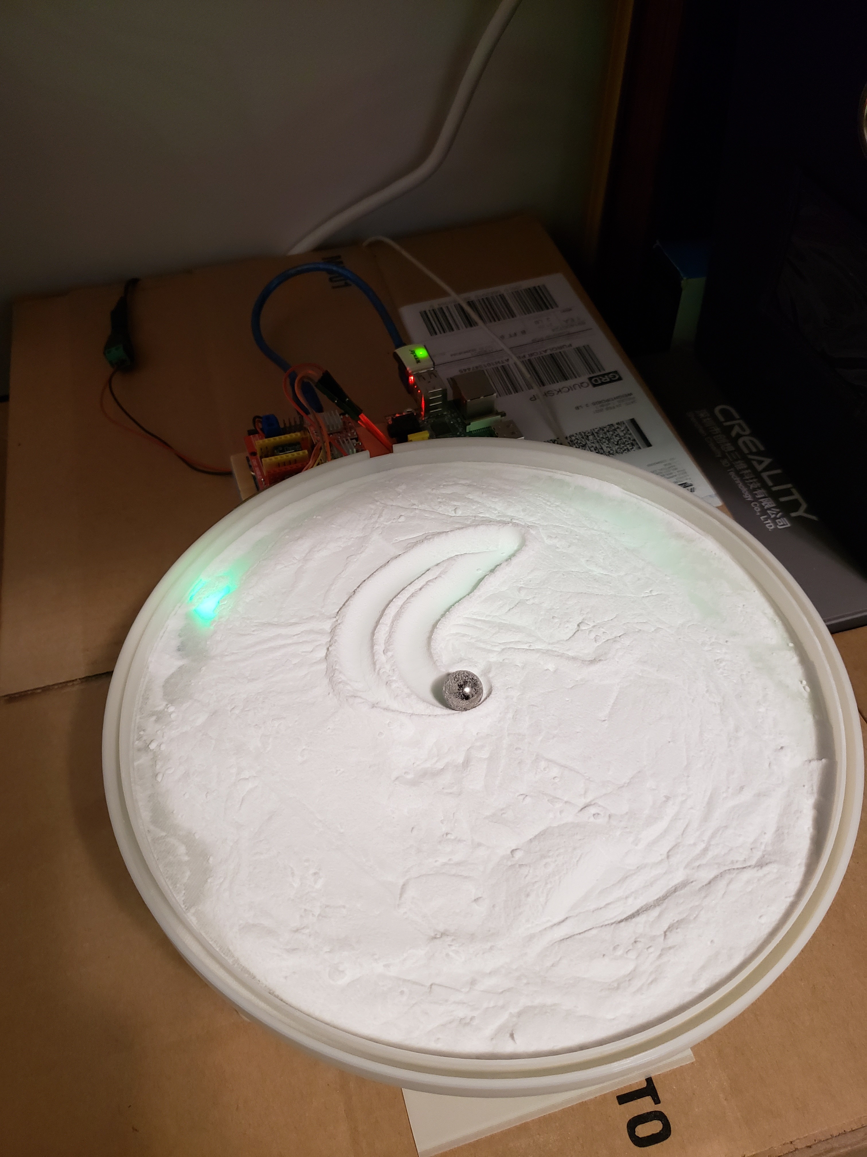
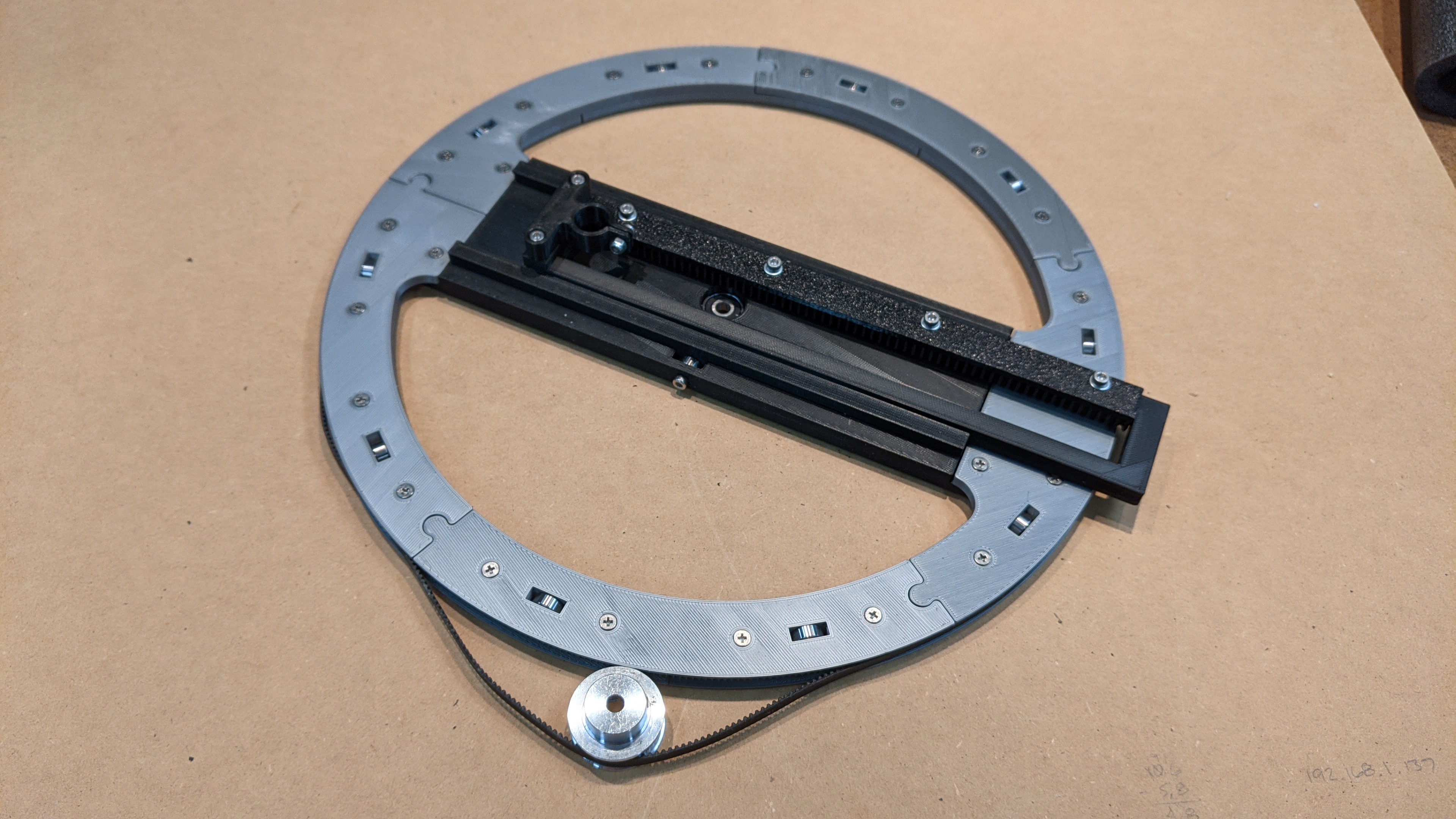
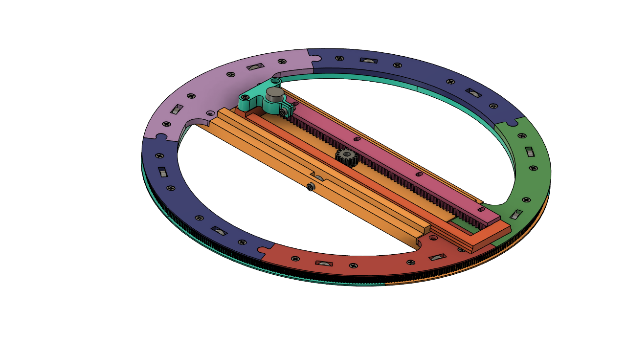
I have made some progress on my version of the Sandtrails. I wanted to try using a G2T belt to drive the theta stage so I thought that I would just 3-D print the entire stage. By printing it in halves I could sandwich some small bearings inside making a ‘Lazy Susan’ type configuration. The Rho stage is also 3-D printed. I made the pinion rack replaceable/adjustable so that I could try out different gear modules and engagements. I am not sure if any of this will work in the real world but so far so good. I will probably have to ask for some hand holding when I get to the Raspberry Pi and the Python code. I have no experience with either (or any other programming language for that matter). Probably not a great combination for this project but I hope to learn along the way!
I like that a lot. It looks pretty sharp.
Looks awesome!
If you want a simple, slow moving Zen table, I don’t think you’ll need to tweak the gear modules too much. But you have all the options now, so go for it 
My theta stage has 450 teeth and the timing pulley I am using has 40 teeth. I chose a 930mm closed loop belt. I may need to lengthen the belt and add a backside idler to get more wrap (teeth engagement) on the pulley. We’ll see. I increased the module to 1 on the Rho rack and pinion just to make it a little easier to 3-D print the rack. The module 1 pinions are pretty popular on RC cars and are relatively inexpensive.
I bet you will have plenty of engagement with that setup to get enough torque to keep it moving but you gotta try regardless. A little lubrication might also be the trick if it isn’t working well. Very nice looking system you have going there though!
Hey Guys,
my name is Arthur I`m 17 and from Germany.
For weeks I’ve been trying to build this robot and program it. Everything is based on an Arduino Scara Robot that I found on youtube.
So far I succeed in writing a code that for my robot that can calculate all angles to get to a given XY coordinate. After days I got my code to work but now there’s the next challenge in completing my project that I can not solve on my own.
Writing some kind of code that can read in files from sandify and run that code so that the robot moves on its own.
(Typing all coordinates manually and move it is too exhausting  )
)
I hope you guys have any tips for me as there are not a lot of people building polar robots with Arduino.
Happy New Year
#include <AccelStepper.h>
#include <math.h>

AccelStepper stepper1(1,2,5); // (Type:driver, STEP, DIR)
AccelStepper stepper2(1,3,6);
const int enPin = 8;

double x = 200;
double y = 200;

double currentPosition1;
double currentPosition2;

double L = 228 ; //Länge der Arme in mm


double theta1, theta2;

int stepper1Steps, stepper2Steps;
int Joint1Angle,Joint2Angle;

const float theta1AngleToSteps = -13.5; //Unterschiedliche Radien für 1 Umdrehung 360° = steps
const float theta2AngleToSteps = 13.5; //1Grad in Steps?


void setup() {

Serial.begin(9600);
Serial.println("Serieller Monitor");


  pinMode(enPin,OUTPUT);
 digitalWrite(enPin,LOW);

 // Stepper motors max speed
  stepper1.setMaxSpeed(2000); //500-4000
  stepper1.setAcceleration(2000);


  stepper2.setMaxSpeed(2000); //500-4000
  stepper2.setAcceleration(500);


}
void inverseKinematics(float x, float y) {
//und && ??? oder & Beispielrechnung
theta2 = acos((sq(x) + sq(y) - sq(L) - sq(L)) / (2 * L * L));


theta1 = atan(y / x) - atan((L * sin(theta2)) / (L + L * cos(theta2)));

  theta2 = theta2 * 180 / PI;
  theta1 = theta1 * 180 / PI;

if (x < 0 && y > 0){
theta1 = 180 + theta1;

}
if (x < 0 && y < 0){
theta1 = 180 + theta1;

}
if (x == 0 && y == 0){
  theta1 = 0 ;
  theta2 = 180;

}
if (y == 0 && x < 0){
theta1 = 180 + theta1;

}
}

void currentPos() {
  currentPosition1 = x;
  currentPosition2 = y;
}

void steps(){
 //Bewegung zu den Koordinaten

  stepper1Steps = theta1*theta1AngleToSteps;
  stepper2Steps = theta2*theta2AngleToSteps; //Mitte


//1. und 2. Quadrant
 if (theta1 > 0 ) {
 stepper2Steps = stepper2Steps + abs(stepper1Steps); //absoluter Wert
 }
//3. und 4.
 if(theta1 < 0){
 stepper2Steps = stepper2Steps - abs(stepper1Steps); //absoluter Wert
 }
}


void loop(){

 inverseKinematics(x,y);
 currentPos();
 steps();


  stepper1.moveTo(stepper1Steps);
  stepper2.moveTo(stepper2Steps);
  stepper1.run();
  stepper2.run();
}

Welcome. Be sure to also check out the progress from Klaus. He is still working on the build and we can all work together at the same time:
Let me point out a few things you should consider:
- The two AccelStepper objects you have don’t know about each other. If you ask one to go from zero to 1 and the other to go from zero to 10, the first will finish right away. The movements need to be more coordinated to slow down the one that is traveling a shorter distance. If you are using the AccelStepper library I think you are, then there is a multistepper. But when I tried it, it did the same thing.
- A straight line in sandify is going to end up being just the next end point. If you just travel from your current position to the next x,y, your corners will be in the right place, but none of the lines will be correct. They will all be arcs.
- Imagine a path of a square spiral. When you go from a theta of -3/4pi to +3/4pi, your current code is going to go most of the way around, instead of doing the shortcut across -pi. This is why the thr format allows rotation values much larger than 2pi or smaller than -2pi.
About your code running question though:
A. You can start reading information on the serial port (but go faster than 9600 baud, 115.2k, at least). You will also need a smart serial port sender on the computer. Something that won’t just spew the whole file all at once.
B. You can also start by just plopping the file in the code. At least a simple pattern won’t be so difficult, and you can solve one problem at a time.
C. There are also SPI micro sd card readers that are very cheap. There are arduino libraries to interface with them.
D. Consider using the thr format from sandify. I know you have this great xy to theta, theta math. But the thr format is excellent for a few reasons.
- It breaks lines down into small segments. This fixes problem 2 and maybe problem 1.
- It outputs continuous theta values. This fixes problem 3.
- The math will be a lot simpler. Not just because you aren’t going to convert from x and y to theta, but also because you can use normalized coordinates. The code won’t even care how long the arms are.
This is why I went to the trouble above to use the thr files. They really are a great format for polar machines.
I would be happy to help you out to get this across the finish line.
I have made quite a few wooden and acrylic gears even a herribone gear using a 3axis 100 watt laser that I added 2 axis for 5 axis. I used gearotic software to create the gears and then imported them as a dxf file into my cad program where I would povide and offset of .005" for the beam. Worked really well.
Sounds great. I’ll have to check up on the gearotic software… drawing those gears was a bit of a pain.
Do you mean the laser cutter had 5 axes? What kind of gears did you cut with that? Not just the simple planar ones I take it…?
You will love Gearotic Motion. I used it to make a replacement gear for my mercedes wing shield wiper mechanism and a lot of gears for kinetic art projects. You can probally see them on you tube. Here is a small herribone gear half done on my 5 axis set up. Herringbone Gears Laser Cut - YouTubeand some kinetic arts stuff thats is larger. All laser cut gears out of wood or plastic (36) SDV 0043 - YouTube
Dan
and here are a couple more. After the spinner video runs then there is the aperature with about a 20" gear

dan
Beautiful work Dan!
Another temptation to build nice toys 
I don’t quite get why you’re cutting tooth by tooth and rotating the disc while doing so. Why do you do this?
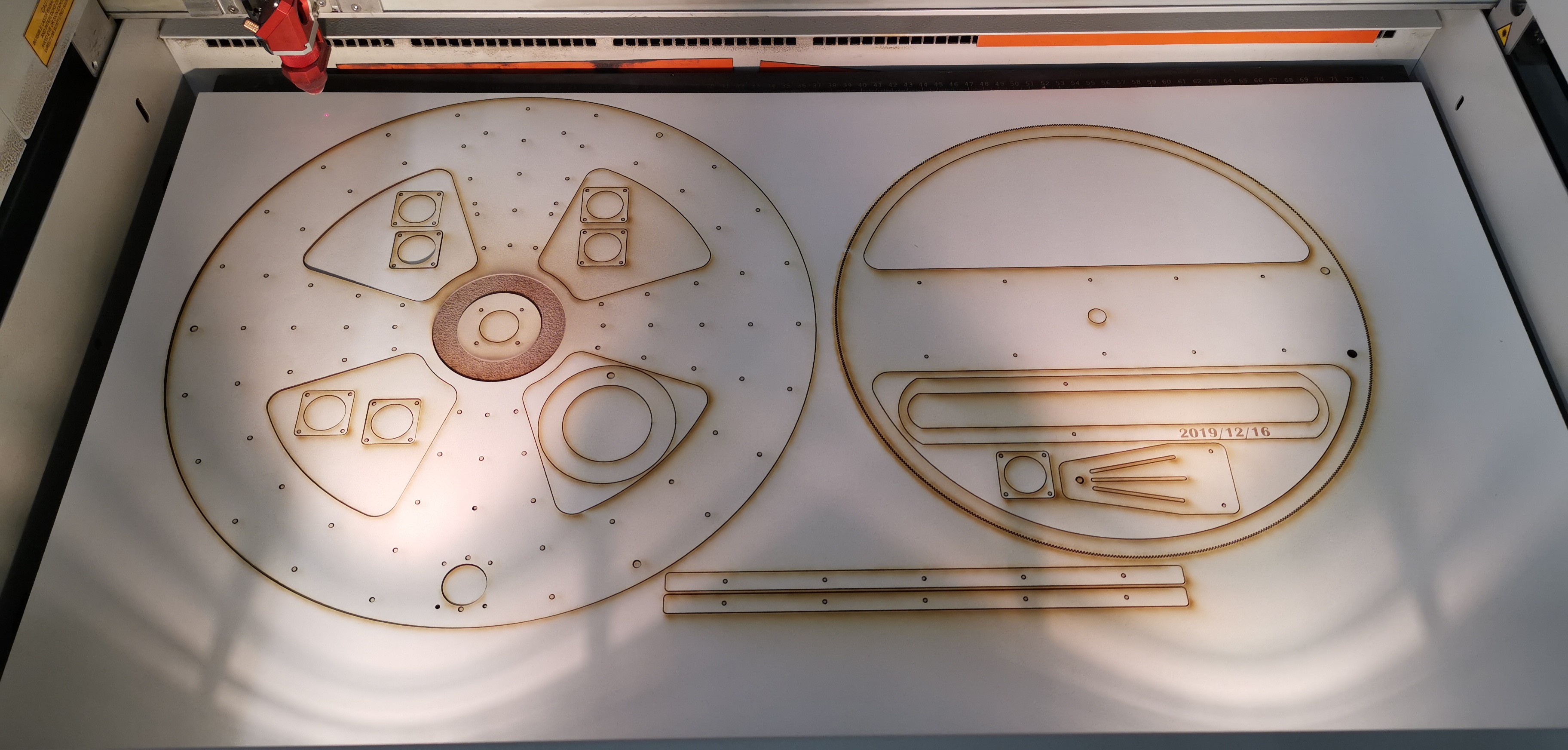
In my naive approach, I cut the whole gear profile in one go with the wood lying flat on the laser-cutter bed… worked reasonably well. My gear teeth are tiny (module 0.5), hardly visible in the overview pic:
The reason that I cut the herringbone gear at a 14 degree angle one tooth at a time was because I was using the 4th and 5th axis. You cannot cut a herringbone gear on a 3 axis machine. To cut a tooth straight 14 degrees was required. So I had a really trick set up. The 4th axis allows allows for the angle to cut a straight tooth then then the 5th axis indexes . I did that by modifying a mouse. I connected it to a relay on of my cnc control box. The mouse pointer is place on the laser software start button. The G code was modified so that a relay would turn on the laser and the control box would than run one tooth then shut off the relay and then index and repeat for as many teeth as required.
Sorry, I had to check up the herringbone gear first. Didn’t really notice the 14deg angle in the video… thought you were cutting “straight” teeth.
That is a cool workaround! I love the DIY way you did that
I was told that it was impossible to make a herringbone gear on a laser. That set up bells in my head and I figured out relatively quickly how to cut the 14 degree and and then make two of them one for the right half and one for the left half then join then using alignment holes in each half. The I had to figure out how to take the software and actuate the program to run the laser. I took apart a old mouse and cut the wires going to the left mouse button and then ran them to a relay in my cnc control box. Last I edited the G code for the single tooth profile by offsetting the tooth width by the laser beam width and then to add a M3 to turn on the laser and a M5 to turn it off. Worked really slick.
I was also told that it was impossible to make crown gears on a laser but I think certain kinds of crown gears could be made using a modification of the herringbone gear setup. But i have too many other projects first.
What is unusual about this piece is the counter rotating shaft setup. When I posted this I asked if anyone knew how I did it. There were a few guesses but no one was close.
Dan
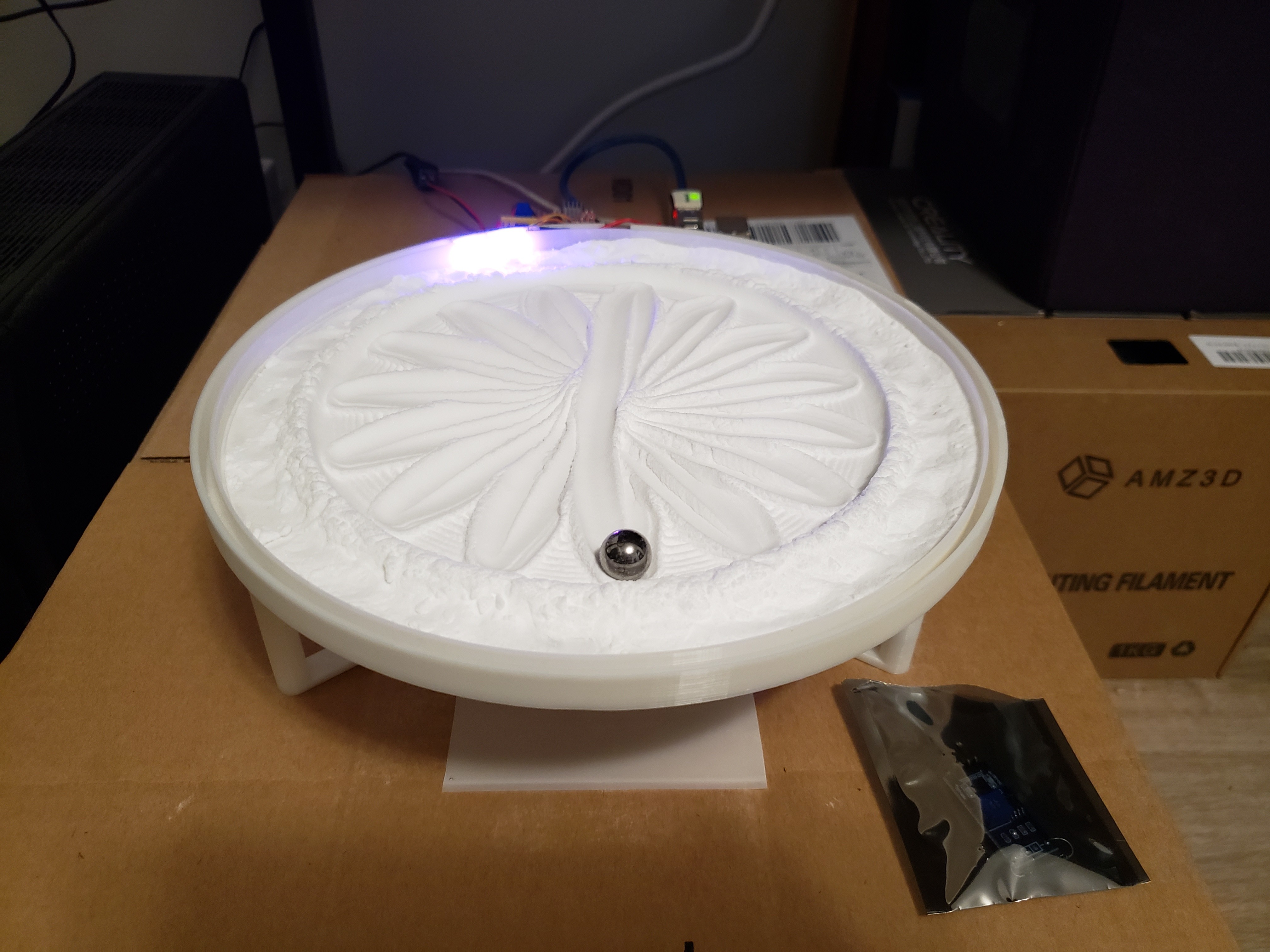
Here’s mine (mini version I designed while waiting on my Aliexpress order for Nema17’s & GT2 belts to start on the Rob D version - 30 to 50 days shipping  )
)
)
I’m using a Pi running Octoprint (with GRBL + LED plugins) to drive an Uno (with GRBL) plus CNC shield, hacked 28byj’s and reed modules for homing switches.
I wrote a script to create the patterns in the picture but, can’t seem to get sandify->jeff’s python script->gcode flow to work (gcode mostly sends machine in circles). Since M2 is directly connected to the elbow by gears, y goes in the opposite direction. Setting y = y * -1 didn’t help. So need to debug that flow.
.py (from Jeff)
m1 = float(theta) + math.acos(float(rho))
m2 = float(theta) - math.acos(float(rho))
x = MOTOR_1_UNITS_PER_ROTATION * m1 / (2 * math.pi)
y = -1 * MOTOR_2_UNITS_PER_ROTATION * m2 / (2 * math.pi)
.thr (trying to print 1st segment of polygon - theta/rho look good to me)
0.00000 0.00000
0.78540 0.02500
0.78540 0.05000
0.78540 0.07500
0.78540 0.10000
0.78540 0.12500
0.78540 0.15000
0.78540 0.17500
0.78540 0.20000
0.78540 0.20001
; # 0.67992 0.18542
.gcode
G92 X0.000 Y0.000 F40.0
G04 P5
G1 X2.070 Y2.070
G1 X3.072 Y1.002
G1 X3.039 Y0.969
G1 X3.006 Y0.936
G1 X2.973 Y0.903
G1 X2.940 Y0.870
G1 X2.907 Y0.837
G1 X2.873 Y0.803
G1 X2.840 Y0.770
G1 X2.840 Y0.770
; 0.67992 0.18542
I can’t wrap my head around these gear mechanisms. Can you maybe show what happens with a simple few commands, like this?
G90
G1 X0 Y0 F40
G1 X0 Y1.5
G1 X1.5 Y1.5
G1 X1.5 Y0
G1 X0 Y0
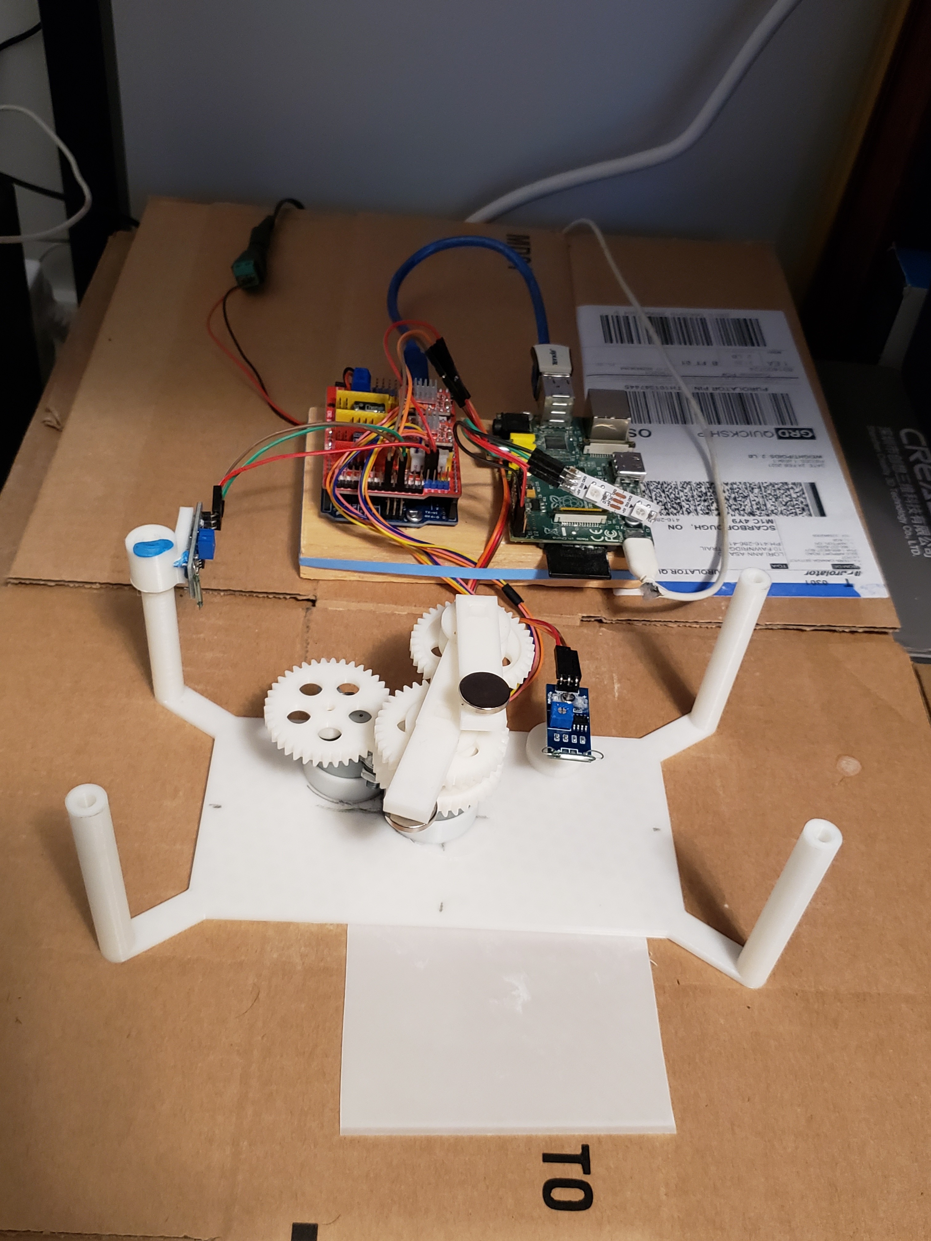
Looks like direct drive. Omitted the belts. Sized gears to arm lengths. Small step motors must run in reverse I figure.
It’s nice and compact. Nice work
Sorry, messed up earlier.
M1 (shoulder) and M2 (elbow) run in the clockwise direction for positive X + Y.
M2 (left side of picture) goes clockwise for positive Y and drives the lower + upper gears (fused together) on the M1 shaft in a counter-clockwise fashion and that drives the gear on the elbow in the positive direction.
I quickly modified the .py file, removing the '-1 * ’ factor but it didn’t help.
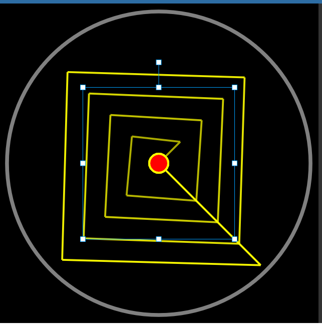
Jeff, I ran your simple pattern.
Here’s the result (the ball started and ended on X0 Y0 but went outwards/to the left and then back inwards before returning to the original