I’m hoping you all can sanity check the 120v side of my MPCNC Primo build.
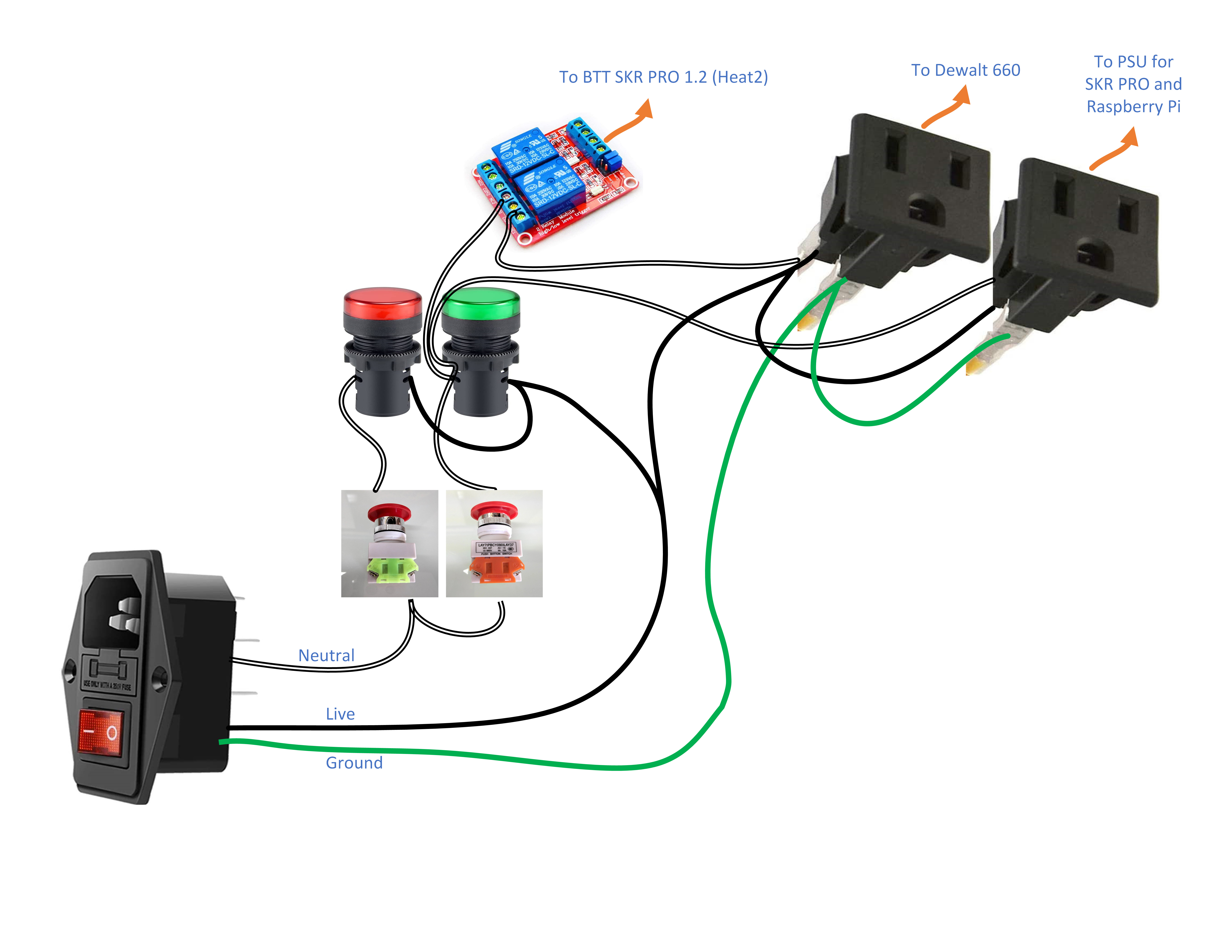
My plan is to have mains power come in through a 120v panel mount socket. The neutral goes to an emergency stop button with red/green indicator lights. When the button is closed the red indicator is on, when it’s open the green. When open the neutral splits - one to a relay for the spindle, and the other to the PSU for the SKR Pro and Raspberry Pi.
What I’m hoping to accomplish is the emergency stop button will cut all power to everything, then have a relay switch to enable M3/M5 spindle control while having unswitched power for the low voltage side.
I don’t know electrical schematics so I whipped up a simple graphic to visualize my wiring.
Does anybody see any glaring issues? I haven’t wired anything up yet since its not a simple low voltage build. I have a healthy respect for 120v and don’t want any surprises.
In another forum topic concerning using a relay for switching the router, it was suggested that a different relay might better handle the surge current from the router. Something like this.
As Dan said, keep switches/fuses on the HOT lines, never leave them straigh-through.
Also keep in mind the proper connections for the hot/neutral lines. While looking at the plug socket for the router, the larger vertical opening on the left is for the neutral and the smaller opening on the right is for the hot.
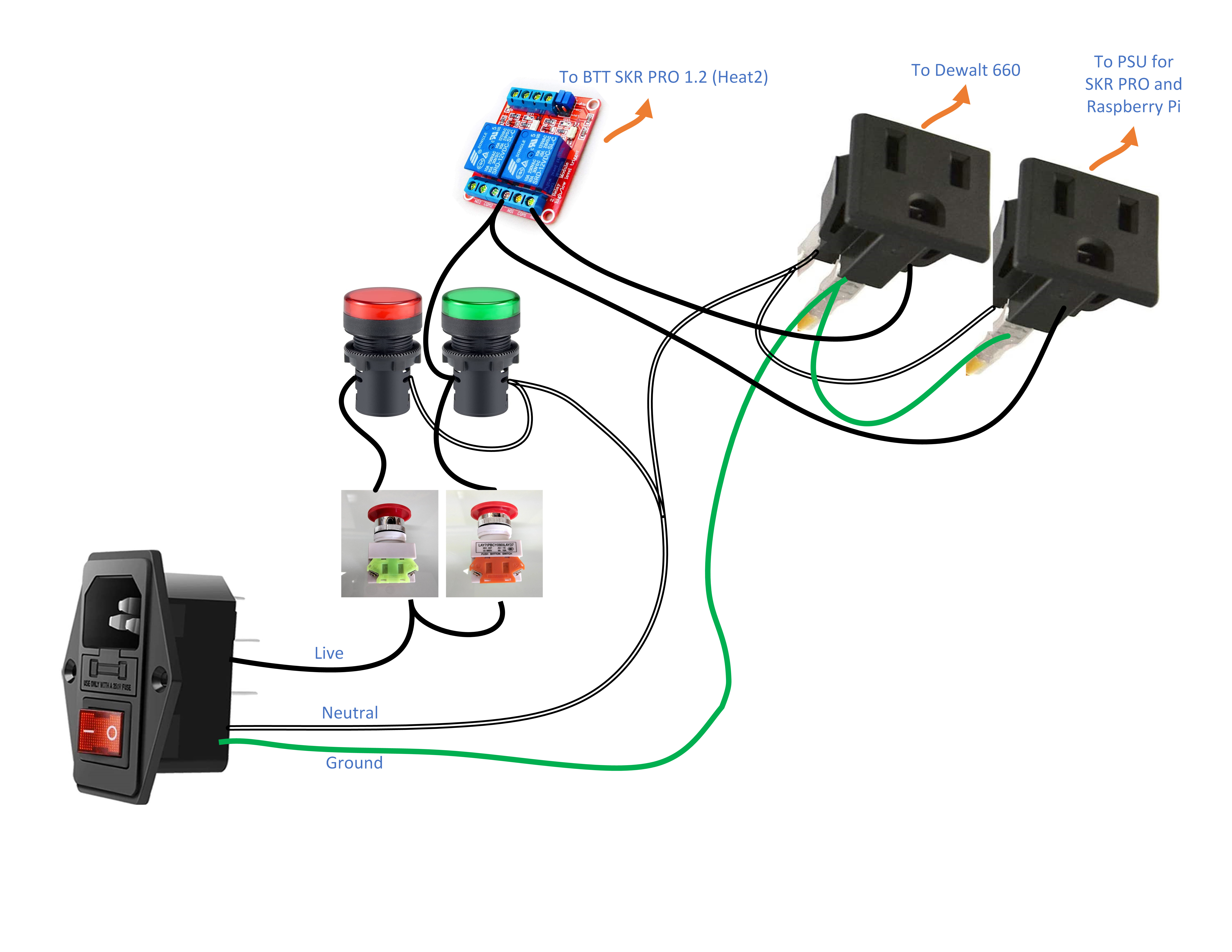
I thought you were supposed to switch on the neutral (white) wire, like in house wiring. Having the emergency switch on the live side makes sense now that you mention it because the plugs would still be energized.
Okay, I’ll whip up another drawing (I’m a visual thinker) to be sure. The plug socket in the picture is at an angle that doesn’t show, but I would have the live on the smaller blade of the plug.
Ideally you would want to make use of double-pole switches/relays to break the connection for both hot and neutral - since ground would be continuously connected.
But when you don’t have that option, always put the switches and stuff on the hot line to disconnect it.
Even if you break the connection for the neutral line, the hot line can still make a complete connection to ground and bite ya.
Not too sure about that. I’ve never gotten into house wiring. I understand how the wiring should be done, and the theory behind it, but as far as house wiring topology, I have no clue.
I live in the US and every house I’ve ever lived in switches the hot line (black, sometimes red) wire, not the neutral (white) wire. Fuses/circuit breakers are on the hot line as well.
Same. Plus, gut reaction is to switch on hot, and be wary of neutral. Those e-stop buttons are nice because you can stack connectors on them that are electrically isolated so one button can make/break multiple connections. Although I wouldn’t necessarily trust too many connections, especially at mains voltages/current…
Of course, this is from the guy who determined that the dentist’s chair in the flooded office he was helping empty out was still live by the tingling in his calves when he got close to it…
I barely understand DC electrics, so I’m just clarifying…
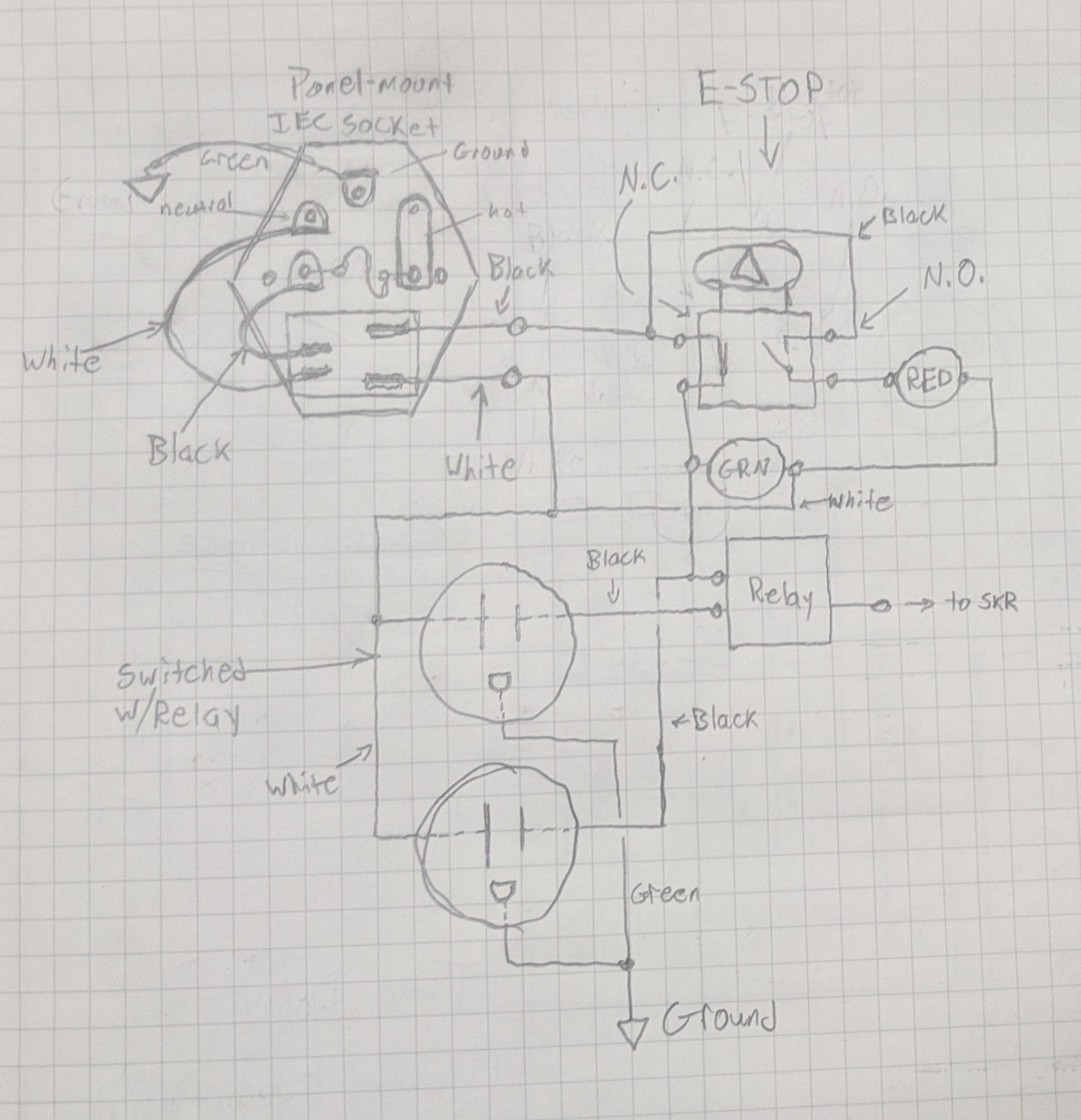
When the e-stop is hit, the circuit is switched over to just a loop through the red LED? Unless something else is wrong, and it’s shorted to ground through one of the two outlets…
Pretty much.
The E-stop is physically two separate switches. One is “Normally Open” and the other is “Normally Closed”. That way when the plunger gets hit, it “opens” one and “closes” the other. The one with the red light is nothing more than closing its switch to complete the circuit to light it up.
Yeah, I get the NC/NO thing. I guess I just still struggle with the whole “still connected to the power” bit… You’re not truly isolating the outlets/relay, but short-circuiting them. Maybe I’m just too paranoid around electricity…