yup!
I also made sure that it did the circles and it did those fine
G01 X1.500 Y-1.500
G01 X2.247 Y-0.747
G01 X2.245 Y-0.745
G01 X2.242 Y-0.742
This start is weird too. It shouldn’t jump that far in one command. That looks like a bug.
I would go back to the gcode with only one square. It will be easier than 10. Even though it is still hundreds of lines.
If it possible we have the shoulder and elbow switched? Or their directions are reversed?
From the wiki,
The Joint A is my X axis and the Joint B is my Y axis is that right?
And joint A is the one at the middle of the BOT and the joint B is the Further one
I just tried the motors plugged in each way in each axis with no success.
Single Big Square With rHO 0.gcode (40.1 KB)
Single Big Square With rHO 1.gcode (40.1 KB)
$0 = 10 (step pulse, usec)
$1 = 25 (step idle delay, msec)
$2 = 0 (step port invert mask:00000000)
$3 = 0 (dir port invert mask:00000000)
$4 = 0 (step enable invert, bool)
$5 = 0 (limit pins invert, bool)
$6 = 0 (probe pin invert, bool)
$10 = 3 (status report mask:00000011)
$11 = 0.010 (junction deviation, mm)
$12 = 0.002 (arc tolerance, mm)
$13 = 0 (report inches, bool)
$20 = 0 (soft limits, bool)
$21 = 0 (hard limits, bool)
$22 = 0 (homing cycle, bool)
$23 = 0 (homing dir invert mask:00000000)
$24 = 25.000 (homing feed, mm/min)
$25 = 500.000 (homing seek, mm/min)
$26 = 250 (homing debounce, msec)
$27 = 1.000 (homing pull-off, mm)
$100 = 1618.000 (x, step/mm)
$101 = 1618.000 (y, step/mm)
$102 = 250.000 (z, step/mm)
$110 = 500.000 (x max rate, mm/min)
$111 = 500.000 (y max rate, mm/min)
$112 = 500.000 (z max rate, mm/min)
$120 = 10.000 (x accel, mm/sec^2)
$121 = 10.000 (y accel, mm/sec^2)
$122 = 10.000 (z accel, mm/sec^2)
$130 = 800.000 (x max travel, mm)
$131 = 800.000 (y max travel, mm)
$132 = 200.000 (z max travel, mm)
Sandify is bugged or i am using it wrong. I used your THR to Gcode converter and its working now! Atleast i think it is i will upload a picture in the morning once it is done
1 Like
Spent most of last night trying to figure out what is going on with my bot that it won’t draw a square. Couldn’t figure it out. Sometimes it draws a 1/4 of a circle then it draws a straight line a few times and then just stops. Sometimes it draws a curvy line. Sometimes it draws a check mark.
I’ve reset the bot so many times I can’t even count. I set it to 0 and try Gcode.
I tried the THR to gcode converter and had more success the bot drew some shapes(didn’t really look like the picture the guy posted).
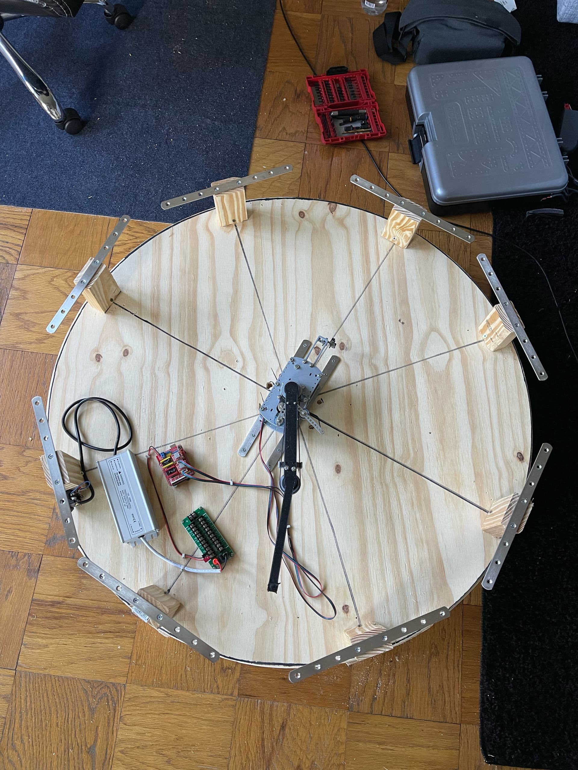
So instead of figuring it out I decided I would move forward and get the table in a more permanent testing solution. There was a lot of sag and everything was a little too uneven the bot would get stuck in certain places or drop the ball. So I made improvements to the design!!! The plexiglass I got is definitely too thin it sags too much in the middle even with all the extra support I tried to give it. Gonna have to switch to glass or metal or something else for the sand plate.
2 Likes
Correct on the on/off nature of the pins. As I understand it. these are digital pins on the Arduino so are limited to sending a single on/off signal message.
Generally, in order to do dimming you need an “analog” or PWM pin on the Arduino that lets you send, for example, a value between 0 and 127, which are then interpreted as relative intensity levels. I don’t know that there are any remaining PWM pins on the Arduino Uno (but I haven’t done research on this). I know that the Z end stop pin is PWM, which is why it was remapped to do the spindle enable/spindle speed feature in later versions of grbl.
I believe that there are different mechanisms for dimming LED’s depending on the circuitry built in to them. I’ve used non- addressible RGB LED strips that take 12V dc and a PWM signal for each of the 3 elements in each “dot” to control color blending and intensity for the entire string. I know that addressable LED’s allow on/off, intensity, and color control of each dot independently, but I’ve never used a set of those myself (although others here on the forums have). I don’t know whether single color strings can be “dimmed” with a simple variable resistor to limit the voltage they get - my guess is probably not, but the documentation for the specific LED’s you’re using should spell that out.
The Arduino Mega (which forms the basis of the RAMPS stack, and by extension the Rambo boards) has more pins overall, which is how it can natively drive 5 steppers and have controls left over for 3 “servo” connections. Servo connections are PWM pins, which can be used to manage RGB LED strips in Marlin by editing the appropriate control directives in the config files, then sending gcode commands to activate the lights.
Hallo
Ich weis wie frustrierend der Bau sein kann, ich hab es selber erlebt.
Was die Sandträgerplatte angeht, habe ich 3mm Aluminium verwendet
Mein Zeichendurchmesser ist 600mm
Schau dir mal den ganzen Beitrag an da sind viele Fehler beschrieben die ich gemachr habe.
Da findest du auch alternative lösungen.
Auf jeden fall würde ich ein Arduino Mega mit Raps1.4 und Marlin verwenden
Ich glaube Klipper würde inzwischen auch funktionieren (da war ein Beitrag hier im Forum)
Servus
klaus
1 Like
BIG UPDATE!!!
I didn’t take any pictures because I forgot to.
So first I went to a hardware store and got some glass it was two mm thick. That was a mistake waaaaayyyy too thin expensive and all it did was break.
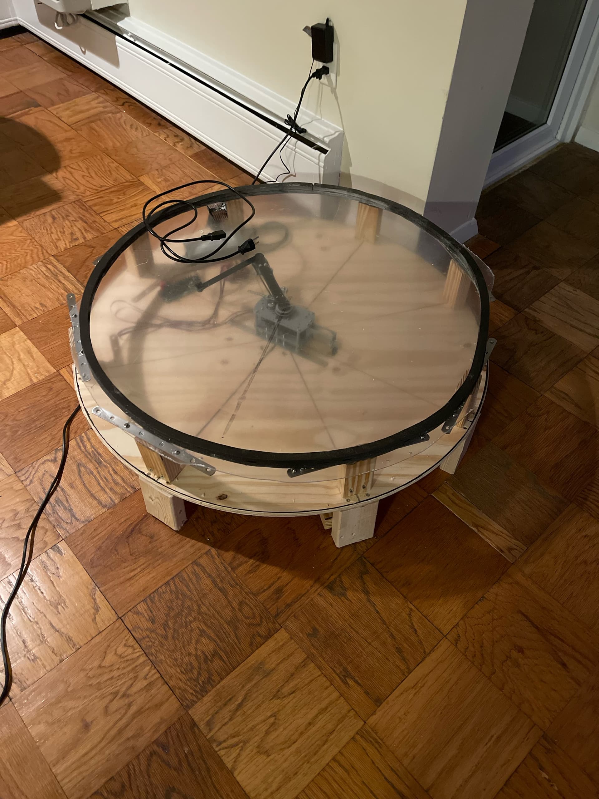
So I found a glass table on Facebook market place for 25 bucks and it was the perfect size. It’s a 36 inch round piece of glass and it’s 5/8th of an inch thick. It’s also tempered glass. I covered the top of the glass in felt.
I’m also starting the process of making the edge for the LEDS. I read that the height part was pretty important so I’m going to try and figure out where is best to put the leds.
I also have three different boards now and I cannot for the life of me figure this stuff out. A lot of the guides are old / not for scara.
The first board I have is a Arduino uno with a cnc shield.
The second board I have is a Arduino mega 2540 with a ramps 1.4 board
And the third board I have is a makerbase mks monster 8.
I was trying to figure out marlin. It’s pretty complicated for someone with 0 coding experience and I get error codes when I try to upload the code for marlin from this website.
I think I’m going to try and figure out the makerbase mks monster 8 today and see how that goes.
Getting pretty close to completion now.
If anyone has any other tips on this scara bot lmk. Again I’m pretty terrible at coding so I really don’t know what I’m doing when I’m editing the marlin stuff
If you want to use the uno, you should use grbl. That is probably the easiest (I thought we were kind of there already?).
The ramps could be flashed with the V1CNC_Ramps from MarlinBuilder releases. Not the easiest way. But it should work. It seems like one of the other builds would be closer, but I am sure the v1cnc is what you’d want. No editing needed, at least until we tried to figure out the endstops.
I’ve never used the monster 8. Sounds like overkill.
Did you see the thread Klaus posted? It translates very well in google translate (I speak zero German). Klaus did go through a lot of pains and you are probably learning a lot of the same lessons as we did in that thread.
So I couldn’t really test it that well because I couldn’t figure out how to get sandify to give me scara gcode that wasn’t bugged.
I resorted to finding gcode that was already made up in scara mode. It just didn’t feel like a good solution to me. I can only use the few gcode files I can find that are in scara format. Maybe I’m doing something wrong with the sandify?
Also some of my end goals are to connect the table to an app / my computer to upload new designs. I’m not exactly sure how to get the Arduino to do that.
I bought all these boards for this table so if one of these boards makes this easier then I’m here for it.
Yes I did see his post!! It’s translates really well with my iPhone. I’m going to spend the day reading through the whole post today. I saw it was 100+ comment thread so I wanted to be able to sit down somewhere and read it really throughly.
Where did you find 3 mm thick aluminum and how much did it cost you?
I bought a Arduino mega and a ramps 1.4 board. Still can not figure it out ![]()
Marlin is complicated. GRBL is definitely more my speed.
Hallo
beim Ramps und Marlin kann ich dir helfen
und weiss wie es funktionieren sollte und sicher auch beir funktionieren wird.
Bei GRBL kann ich dir leider nicht helfen.
3mm ALU hab ich bei mir in der Schule bekommen sollte aber jeden Metall verarbeitende Betrieb für ein Paar Euro bekommen.
servus Klaus
Jeffeb3 du sprichst mir aus der Seele
Also als erstes musst du den Arduino beschreiben.
Dazu musst du den Arduino mit deinem PC über USB verbinden.
Dann vogende Datei herunterladen:
Diese Datei auf den Arduino mittels der IDE software spielen.
Jetzt musst erst in der IDE deinen richtigen Arduino auswählen.
und jetzt die heruntergeladene Datei auf den Arduino spielen.
Jetzt vom USB trennen und Spannungsfei arbeiten.
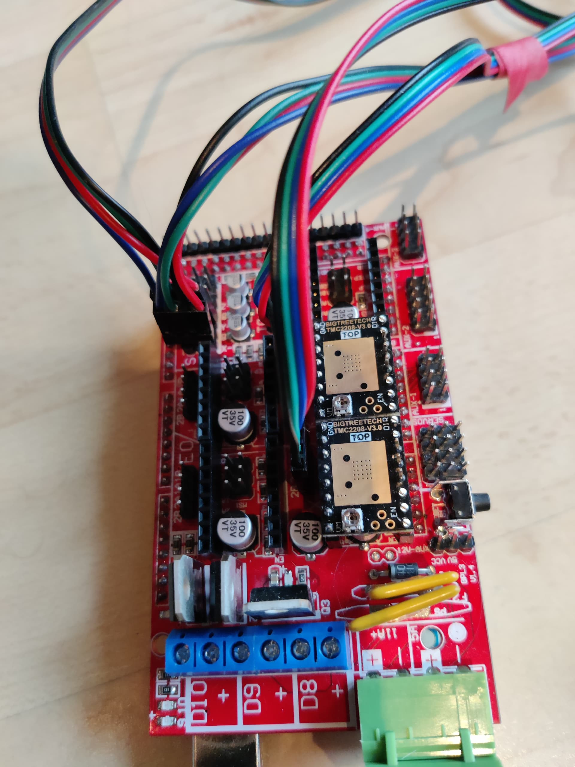
Als nächstes müssen am Ramps alle Jumper unter den Treibern (X+Y) eingesteckt werden.
Jetzt können die Treiber in das Ramps gesteckt werden
Jetzt noch 2 Endstop an X und Y und der erste Zauber ist fast vorbei.
12V Spannung an das Ramps geben
und den Strom an den Treibern einstellen.
Wenn du soweit bist Geht es in Marlin weiter.
Wir brauchen die Anzahl der Zähne am Motor und am Antrieb um weiter zu machen.
Mein Roboter hat folgendes:
- Übersetzung von 20 Zähne auf 60 Zähne auf beiden Achsen
- TMC2008 mit 16 Microsteps
((200 x 16)/6)x3 =1600 Mikroschritte / Umdrehung
Jetzt verwenden wir eine Druckersoftware wie Octoprint um in Marlin deine oben berechneten Microschritte zu speichern.
M92 X1600 Y1600
M500
Jetzt müsste dein Scara betriebsbereit sein.
Wenn du Jetzt Octopi auf deinem PI installierst hast du alles um Bilder auf deinem SCARA-Bot zu zeichen.
Bilder werden auf Sandify erstellt und beim Export auf Thetarho auswählen und diese Daatei dann in Octoprint hochladen.
Dein Glas ist aber gross und dick hab ich gelesen,
bin gespannt was du für Magnete brauchst um die Kugel zu bewegen.
servus Klaus
Hmmm. Ok. Maybe I broke something.
Klaus, have you tried a file recently from sandify using the scara output?
I will try to carve out some time later to look more closely at it.
The backup is to take the thetarho output and run it through the python script I made originally:
Ist schon einige Zeit her dass ich die letzte Zeichnung gemacht habe da der Tisch immer noch im Schaufenster des FabLab der Uni in Bozen steht und dort meine voreinstellten Bilder malt.
Ich werde demnächst meinen Tisch zurückholen.
Ich hab ein paar neue Ideen aber nur zum Tisch nicht zur Mechnanik.
Einen Tisch aus Beton gedruckt in Vornoi Design

Mal schauen ob das was wird.
servus Klaus
1 Like
I did some testing of sandify’s scara output. From the post I linked, the basic math is this:
alpha = acos(rho) * 3 / pi
X = theta + alpha
Y = theta - alpha
The 3/pi just converts from radians to our 6/rotation units.
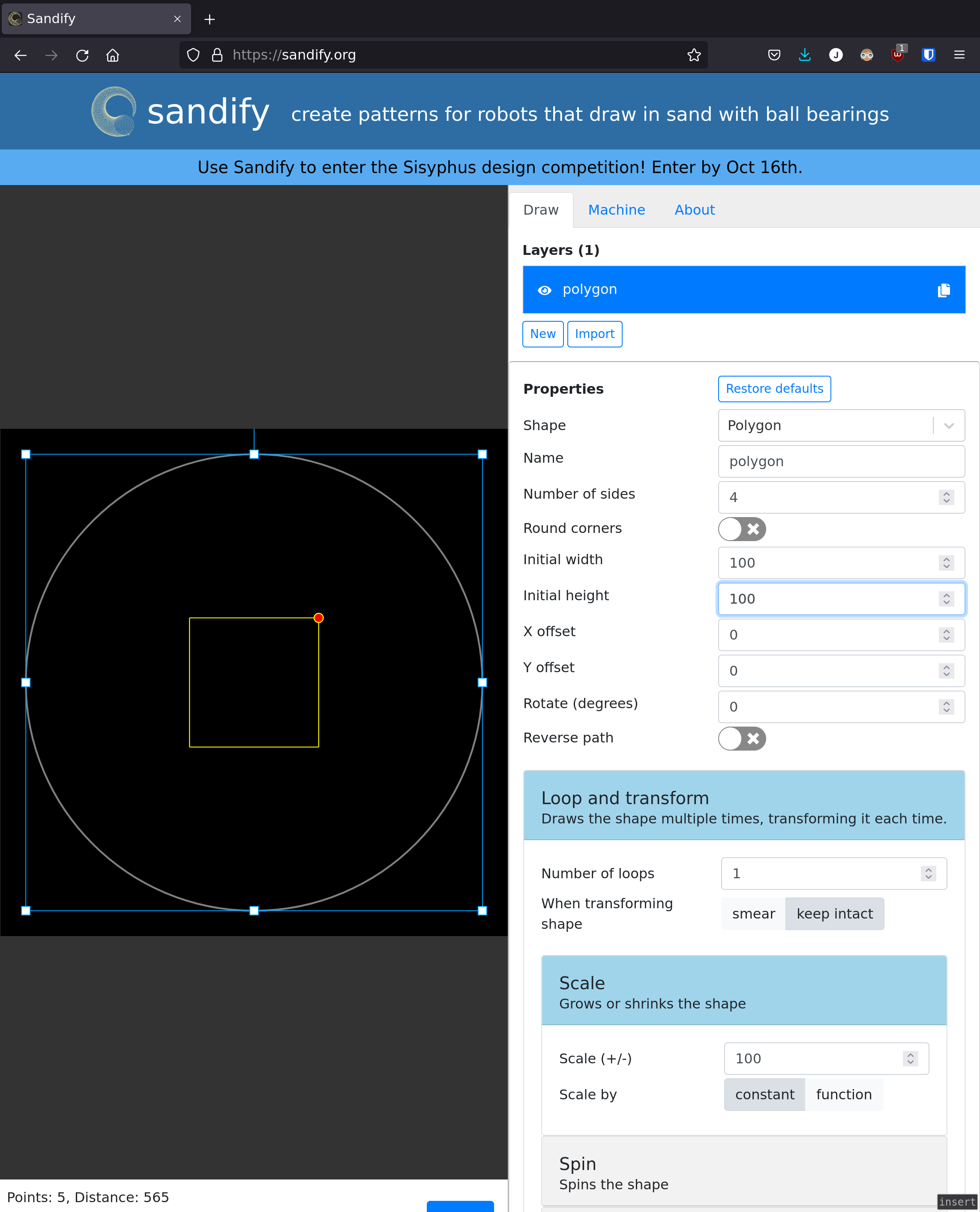
I made a very simple shape, a single loop of a square, 100x100 on a 250mm polar table. I exported it as thetarho (5.6 KB) and scara.gcode (6.3 KB)
thetarho.gcode (5.6 KB)
In the theta rho file, I found the 5 major points (where the rho was the largest):
0.78540 0.40000
...
-0.78540 0.40000
...
-2.35619 0.40000
...
-3.92699 0.40000
...
-5.49779 0.40000
Theta rho draws nothing but arcs, so to make straight line segments, sandify breaks all of the lines into many dozens of coordinates to follow, so there were a lot of other lines in there.
I made a table to convert those key coordinates into scara gcode:
| theta | rho | X | Y |
|---|---|---|---|
| 0.7854 | 0.4 | 1.857 | -0.357 |
| -0.78540 | 0.4 | 0.357 | -1.857 |
| -2.356 | 0.4 | -1.143 | -3.357 |
| -3.927 | 0.4 | -2.643 | -4.86 |
| -5.498 | 0.4 | -4.143 | -6.357 |
I also grabbed the same pattern in scara gcode output. Since the shape is rotating around one way, both motors end up rotating a full circle between the beginning and the end. So these coordinates make sense, right?
-4.143 - 1.857 = -6.000
-6.357 - -0.357 = -6.000
Those are both one full rotation from start to finish.
And just scrolling through (I am just scanning the X values to look for matches and checking the Y values), I see these lines:
G01 X1.857 Y-0.357 ;;
...
G01 X0.357 Y-1.857 ;;
...
G01 X-1.143 Y-3.357 ;;
...
G01 X-2.643 Y-4.857 ;;
...
G01 X-4.143 Y-6.357 ;;
I added the ;; comments to make it clearer.
That’s doing exactly as predicted. Which isn’t a surprise, because I am only confirming my own model  . The question remains, why would the gcode you found that went through my scripts be different than the gcode that you’re getting from sandify? Maybe there is a setting missing? Maybe there is a procedure that is missing?
The grbl controller should work very well for you. I don’t think trying to write any embedded code is the solution. We just have to figure out what is wrong with the gcode generation, or the procedure.
1 Like
I’m at work right now I will open sandify and try it here maybe it’s something with my computer at home?
I’ll upload the file in a min
I’ll screenshot all the screens too.