Of course. I’ve never built a Scara, so I’m interested. I ordered parts for the standard ZenXY, but this polar version intrigues me. While the design on top is interesting, the left brain wants to see the underside. Looking to create a design that highlights both.
I’ve been thinking about making something like this for a while, and your build looks like one of the best I’ve seen. I have a few questions/comments…
- how fast do you run it? I think you said the bottom of the sandbox was aluminum. I am curious if you’ve run into any speed limitations due to the moving magnet inducing current in the aluminum.
- does the magnet contact the bottom of the sandbox? I’m always concerned about a cantilevered arm being rigid enough to keep the magnet off the bottom of the sandbox.
- I am not familiar with Octave- is that a program written specifically to process pattern files? Can you post a link? I like the preview image it generates!
1 Like
I can answer the question about octave. It is open source software that sort of replaces matlab:
It has a simple scripting language. It focuses on doing mathematical operations. A lot of the code above uses vectorized operations, which work on each element in a vector/array. It starts counting at 1  .
.
1 Like
I usually do 100mm/s or less, after that it looses the zen for me. It does 200mm/s with a motor drive current of only 0.15A
Buuut you made me curious on what the limit would be. I removed the baking soda to try chinchilla sand and while the table was empty decided to test the limit…
Turns out, with 1A I can do F720 around the perimeter. That translates to 2 rounds per second around the talbe or a bit over 3000mm/s ![]()
No, the arm is not rigid enough for that, and it is not intended to be. I believe all scara tables have some form of glide pad on or near the magnet. The arm just clips to the underside of the box when the ball is placed and glides along.
As Jeffeb wrote, Octave or Matlab is more a mathematical toolbox.
I abuse the plot options it has, to get the preview with overlaping tracks.
- Plot the track in 3d by using an increasing vector as z.
- Plot the track a second time, this time with an onffset for the z values and thinner, darker line
- view from the top
- profit

2 Likes
Any videos of the arm in operation? The sand is cool, but we’re all geeking out about the mechnical.

Ok. That is very satisfying to watch.
So cool. It’s too bad you put sand on top of that.
Does it always hold a counter-clockwise bend in the second joint? I realize it needs to reach a fully extended distance to be allowed to unfold itself. It’d be fun in the pattern to detect a fully extended point and flip the elbow to the other side.
Have you considered using a counterweight so that it isn’t cantilevered? You could then counterbalance both joints. This way, the motors simply have to overcome inertia.
Or do two magnets on opposite ends of the final arm that now extends in both directions for possibly very interesting patterns.
1 Like
Yes, at least when using sandify output. Switching directions on the outside doesn’t provide a drawing benefit, but switching bend direction when moving through the center could reduce central arm movement. @jeffeb3 that would be an nice to have sandify feature ![]()
I considered that for the central arm, that’s why there is an extension there. Turns out the arm is stable enough without it and the torque on the central bearing doesn’t add significant motor load. Adding a counterweight would just increase the inertia.
I arbitrarily chose one direction for the bend. I agree that it wouldn’t make any difference to the extended case, but at the center, I could decide to flip the bend direction if that ended up in a shorter path.
I’ll have to think about that.
I don’t have a scara table to test it with.
2 Likes
I volunteer for the testing 
1 Like
I am done with the config files for now.
Here they are, as requested by @Breslauklaus
klipper scara config files 20220730.zip (6.4 KB)
Several macros are included. Most intended either for use with physical or sofware buttons.
Functions include:
home
pos_norm: SCARA specific - resets the arm positions to near origin - use between prints or in START_PRINT
accelerate & decelerate: increase / decrease relative speed per button push
start_pause: intended for physical button - starts a random drawing when not currently printing, pauses when currently printing, resumes when paused
pause_cancel_wipe: intended for physical button - pauses print when printing, cancels print when already paused, starts a wipe if already paused
continuous_print: toggles continuous drawing of random files from list (with defined pauses) (requires END_PRINT line in the gcode file)
cycle_printgaptime: changes the pause time between prints when continuous print is active
LED related when using Moonshine:
cylce_animations: changes LED animation type
3x LED brightnes related macros
some of those macros use stored variables that have to be initialized once after firmware install
variable_initialization: writes variables to file (may not contain all needed variables)
Hope this helps if someone else decides to build a table running klipper 
1 Like
Just saw this thread and gotta say I’m impressed all around… very well executed project!
Hi @Dito, really nice looking table you’ve made! Intrequed that you’re using klipper for running the arm, that made want to make one aswell. Im currently designing my own arm, heavily inspired by Rob’s design; This is my first real electronics project i’ve tackled.
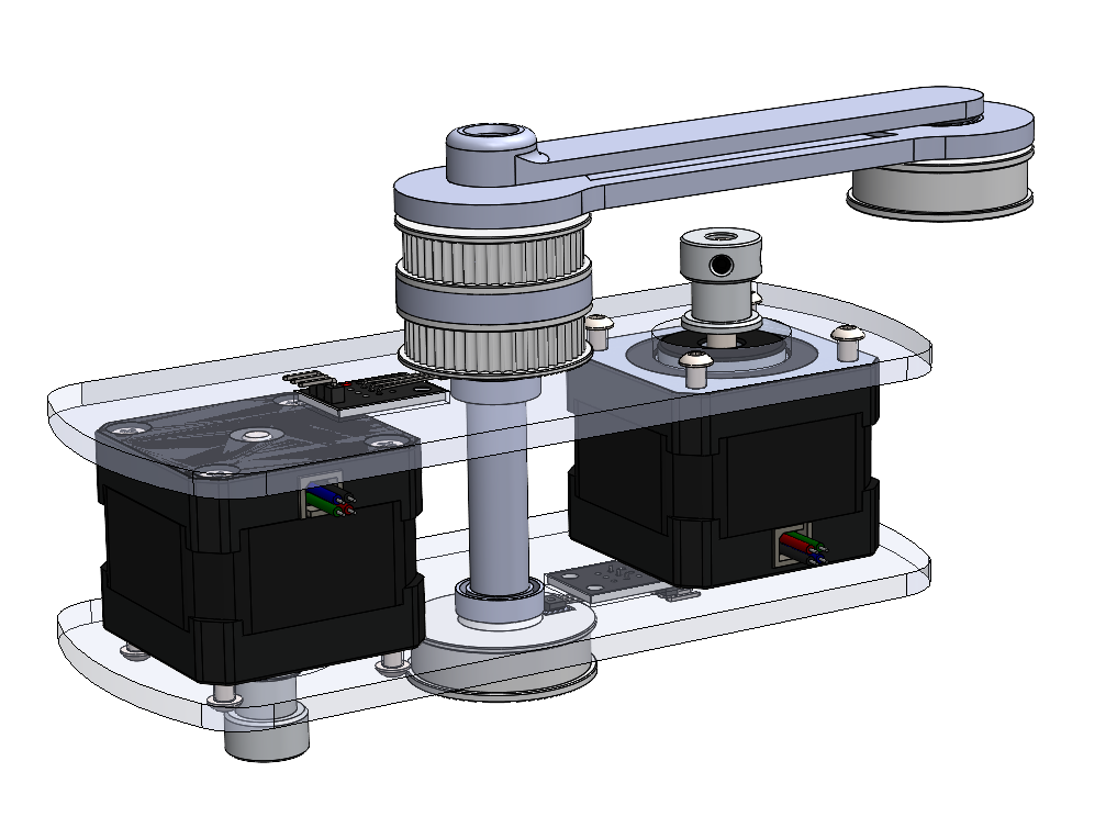
Looking at the electronics from your table, and then mainly the picture from below, it seems that you have quite alot of electronics built in. Do you run anything else specific for this arm on the raspberry pi? I currently have a 3D printed which i’ve adapted from Marlin to Klipper and would be looking using the same pi to run my own arm. How did you define the parameters in your klipper config file, for example the rotation distance? Im using a 16T pulley to a 48T pulley, using a GT2 belt. Looking at your config, would it be 16/48*6=2 for the rotation distance?
What are your parameters for creating the patterns in sandify for your specific table? I assume you use the SCARA export function in sandify?
2 Likes
Hi Max, glad you got inspired, it is a fun project ![]()
I use the PI GPIO for buttons and led control, thats all. It just looks intimidating because it is such a mess of wires ![]()
Yes, 2 is right for a ratio of 16/48 and default setting (6 units per circle) in sandify.
Endstop positions are different from table to table, just make sure that the arm is fully extended for x=0, y=0
min max positions for x and y should be huge to avoid running into software limits when drawing.
The rest of the movement settings are a bit of iteration and personal preference. Just find values that work reliably and you are comfortable with.
I also have a section in the config files that adds G0x command support to klipper - this seems to be no longer required with the latest version of sandify.
Sandify settings are on default for a Scara table:
Export as: scara
max. rho value: 1
Units per circle: 6
no program start or stop code, I handle that in Klipper
For the mechanic design: I would reccomend to add some form of belt tentioning to simplify assembly and avoid backlash. Backlash would distort your patterns whenever a arm direction is reversed, resulting in lines with bends where the souldnt be any. Jeffeb has investigated that for some other scara table.
Good luck with your project.
3 Likes
Awesome, thanks for your reply! Thanks for the tip regarding the belt tensioner, will be integrating it into my final design. I got my endstops integrated into my pulleys, inserting small magnets that switch the hall sensors. I will be sure to have the arm be extended fully for its home position. Why is that necessary if i may ask? I assumed a home position in the actual middle of the table would be prefered.
Looking forward impressing my wife with a self drawing table!
sandify just assumes the origin on the outer diameter.
You can home to the center, but the endstop offsets then have to be set to e.g 1.5 and -1.5
The origin has to be correct, otherwise the designs exported from sandify will be distorted until unrecognisable on your table.
Dont worry too much about getting the magnet position right. Just fine tune the endstop offset in the config until it is perfect. Easiest way to check if you got the relative positions of the arms right is to actually move to the center with G1 X1.5 Y-1.5.
If the magnet is over the central shaft, the arms positioning to each other is good.
Rotation of the coordinate system can then be modified by adding an additional offset to each endstop offset value.
Edit:
see the Scara section of sandify on github for more information about the arm movement definition:
https://github.com/jeffeb3/sandify/wiki/Scara-GCode
3 Likes
You’ll be hearing from me when i have my build ready to set up! Thanks for the tips, appreciate it 
2 Likes