So, I checked the screws and they are all very tight without any play.
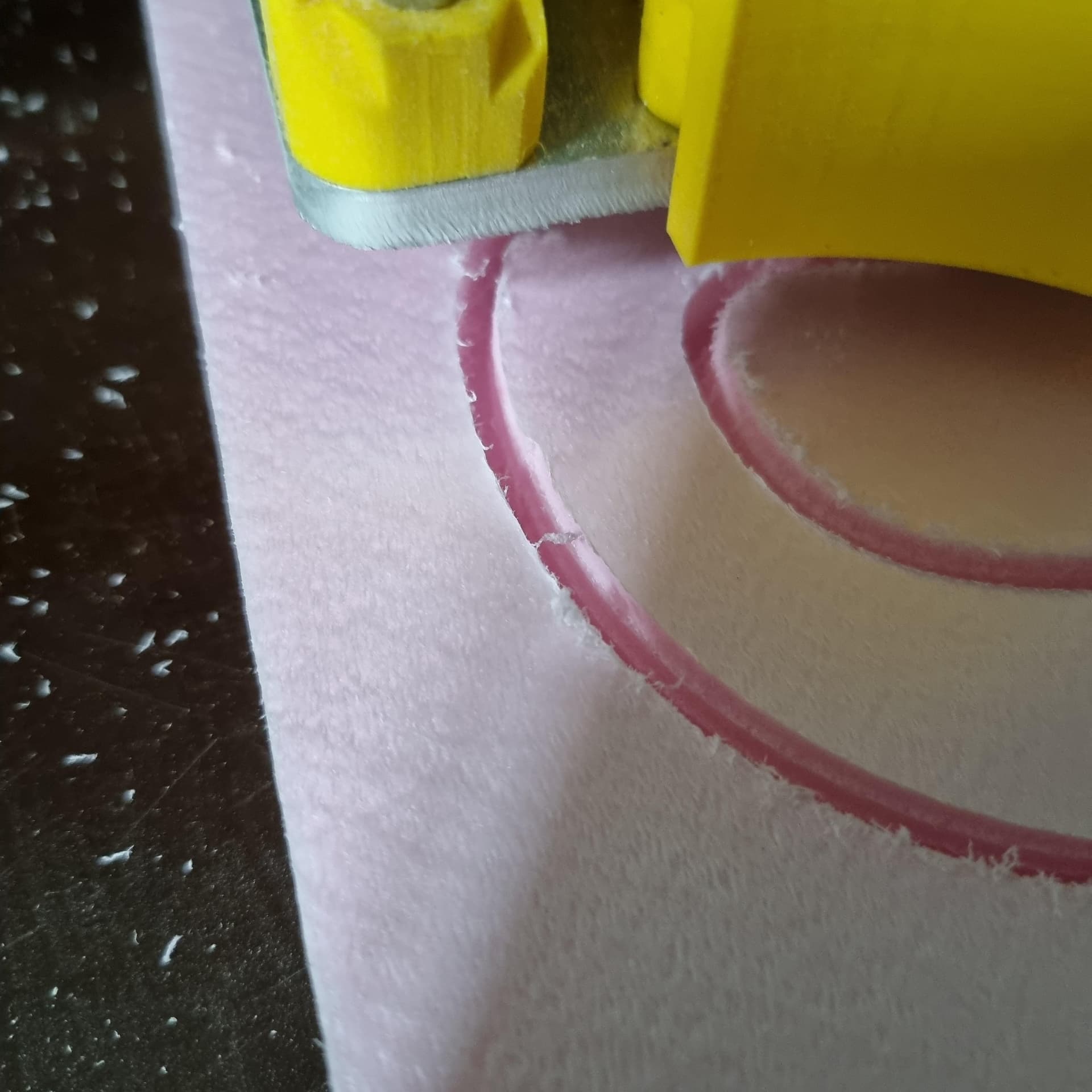
I changed the milling method but that ran into an issue where I had to kill the job (damn that was scary). It got jammed on the inner circle of the letter O, probably because I did not use any holding tabs. But that wasn’t an issue before using the conventional way of milling, so will need to experiment there.
I still need to finish my machine, as I did not make any more progression to where I left in my build log. So I will definitely look for a temporary solution to guide the wheels like Jeffe suggests, and try once more.
I know you´ve already mentioned it elsewhere to try some tracks, so it is on my list as an upgrade. But haven´t had the time just yet to actually do it. Not sure if I should move this up in my priority list. I still need to make a flat workarea too
I have been experimenting with the conventional vs climb milling.
It seems to have some impact too…
This is conventional milling; see how it travels layer by layer.
That´s a big difference as you can see. It is exactly the same job, just different way of milling.
However… the climb milling is causing multiple issues on my machine making it unusable.
It jams on area´s where the mill is cutting close to a previous part, or when breaking through my piece of wood onto the spoil board. And I also noticed it breaks layers of MDF easily causing a jam once again.
Did you have this issue on all your jobs?
Because, what I do notice is that a simple square or triangle cuts just fine (using conventional milling). But when using more curves or a longer piece (30cm or so), the issue starts as soon as it cuts the second layer into the wood.
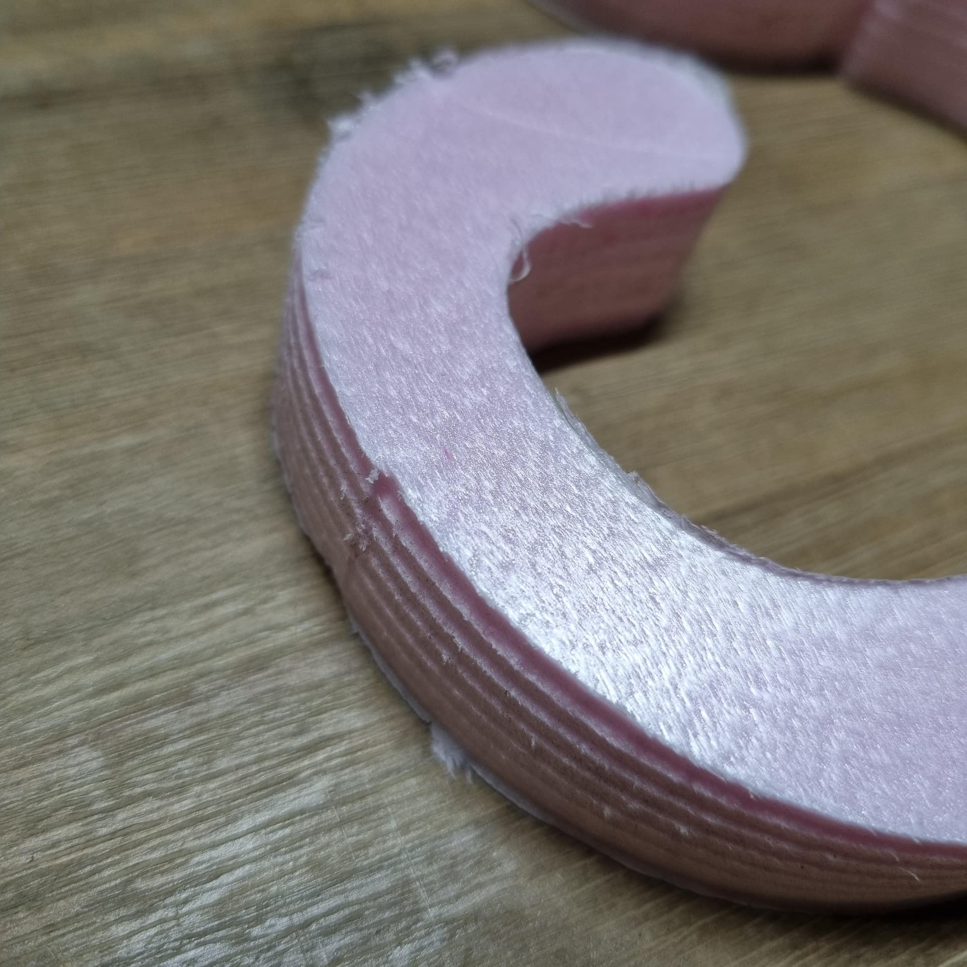
The nail in the coffin for me was cutting the purple High Density foam from Home Depot (HD foam). I had the stairs appear there, where there was zero load from the material. If that couldn’t cut straight, then the machine was doing it to itself.
Conventional vs. climb makes it go clockwise vs anticlockwise (I can never remember which is which). So that further supports the idea that the machine has a bias in the X. Because the direction it travels would change which way the X slop would go.
I didn’t spend any time trying the machine before attaching some strips of wood. My Brad nailer was already loaded and nearby. One quick trip to the table saw to make some strips and a few minutes to tack them down (I didn’t use glue, they don’t have to be strong, just in the right place so it won’t jam). The next cuts in HD were perfect, and I haven’t looked back.
YMMV. This is all just my opinion. Many people have no issues with it.
a follow-up;
it has been hard to find “HD foam” in my area so I settled for XPS polystyrene panel.
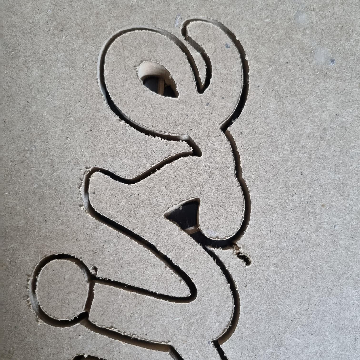
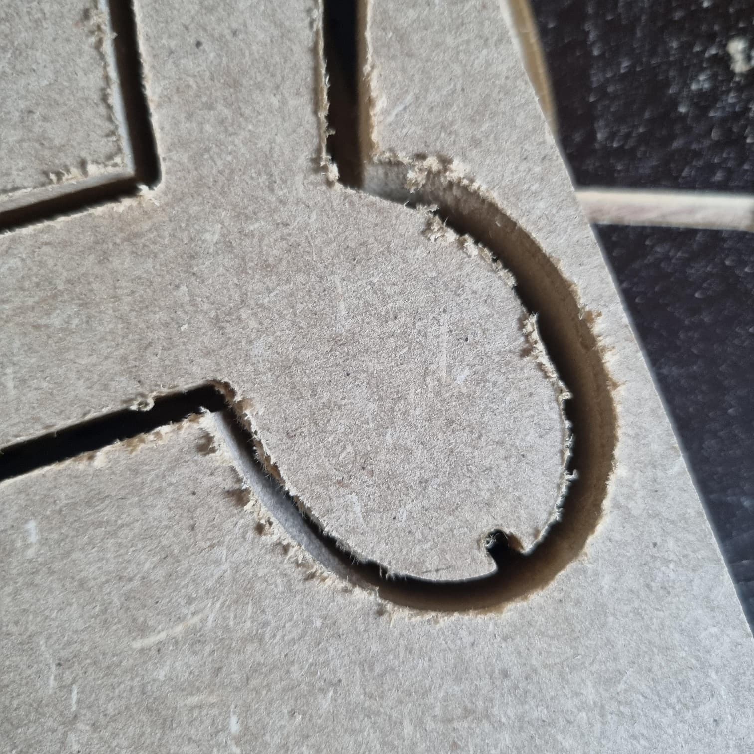
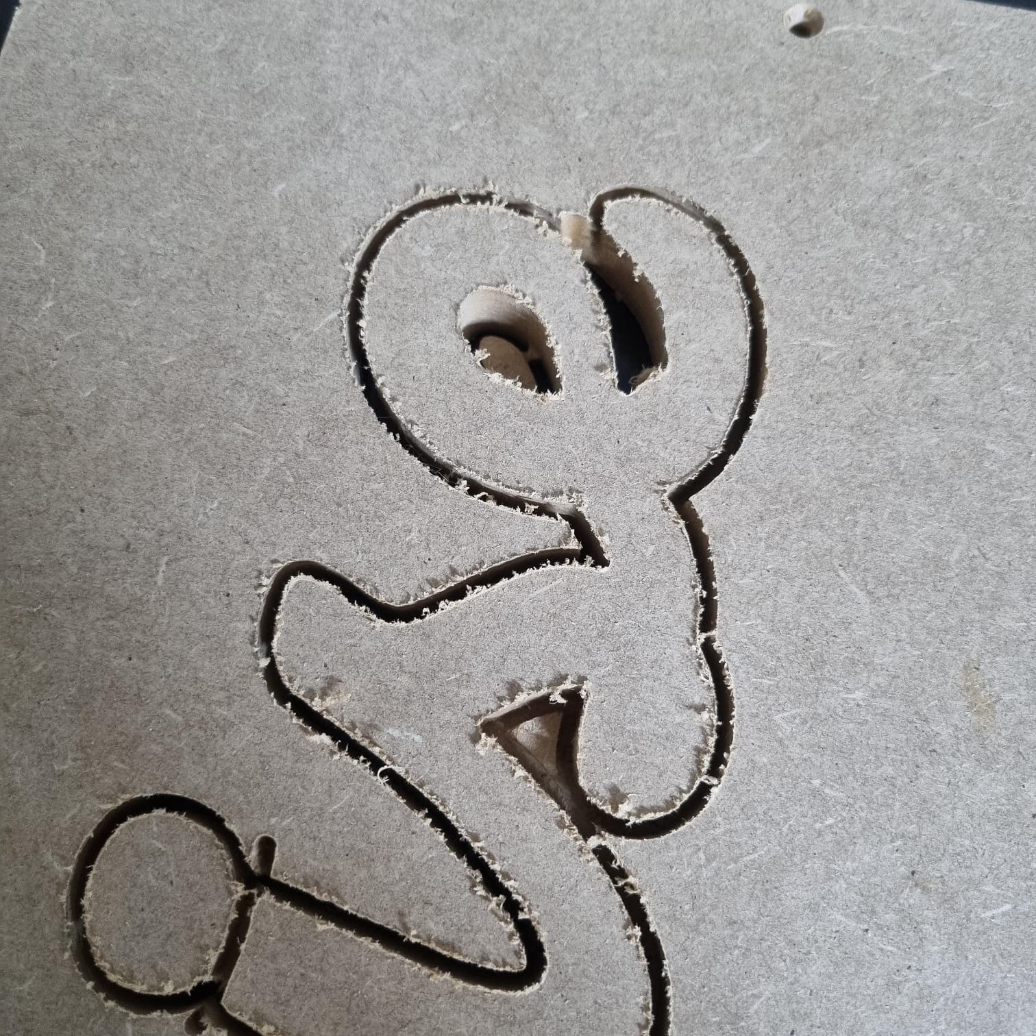
Using the exact same gcode, it becomes clear that the used material doesn´t make a difference. The moment LR2 started a second pass the line was no longer aligned.
It´s becoming clear to me that the L2 moves sideways on the table.
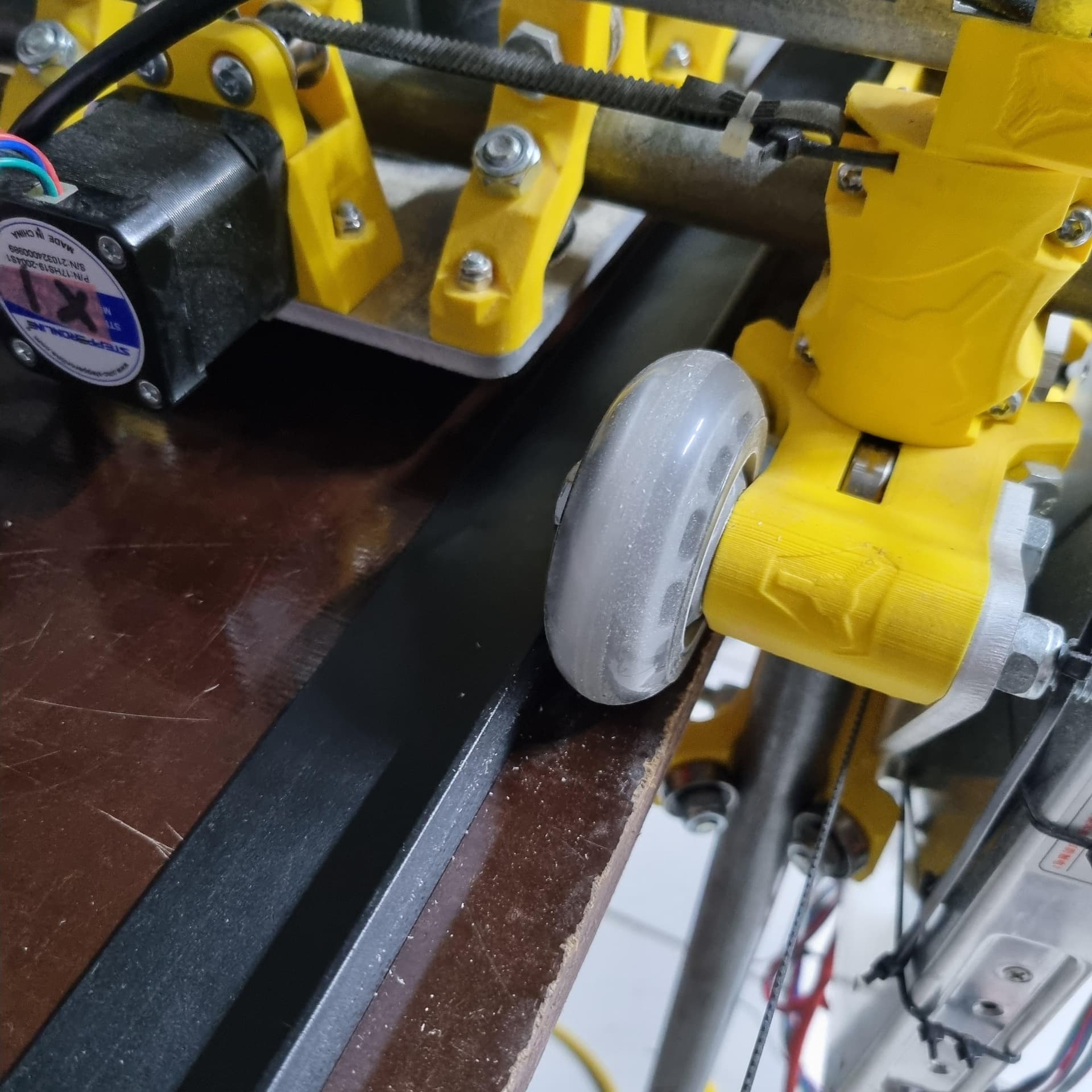
Some dust remained from a previous job. It made it easy to track the direction the wheels roll. As you will see, the line gets wider where the part is been milled.
Will see if I can add a wheel guide for now, and if that fixes my issue, I will upgrade it completely, to use something else then skate wheels. I am just a bit worried that maybe the XZ_Main isn´t square. If that´s the case a wheel guide will not make a difference.
Some of these LR2 builds just like to walk sideways, it’s one of the issues the LR3 is addressing.
I have a bit of work in on adapting the LR3 fix to the LR2, but it’s not complete.
I think that some constraining strips inside the wheel tracks are likely to resolve your problem. The X axis travel will bind if the rails arent good, and if it’s a little out of square, the constraining strips will at least make your tool path repeat reliably until you figure out the squaring issues.
You can also to a really quick test to make sure you assembled it square. Measure the distance between the back wheels and the front wheels. The distance should be the same. if not, it will want to make a giant circle.
A second possibility is you are not starting square and you are hitting the side of your table, basically driving crooked.
A third is you are just trying to move way to fast, rapids and cutting speeds.
If the distances are very accurate, and the rest check out, you can add a rail like Dan suggested.
The other thing you have not mentioned is if you are wired individually, series or parallel. What board, what drivers and what current are they at.
There are a ton of things that can cause this sort of thing.
Another thing to try is air cut the entore parimeter of your piece to make sure there is noe wires or cords snagging, and offset will happen on the first lap after that it should cut fine.
Your climb vs conventional is making this all seem very odd, like you might actually just be moving to fast.
That is the part that makes me think it isn’t tracking straight. The results are different in clockwise and anticlockwise directions. The drift is in a different direction.
I guess it could be, such a weird one. The machine still has to make the same moves, just ends up being on the other side of the table. Clockwise vs counterclockwise on a circle still gets a circle, but you do have experience with this. I could never get mine to do it.
Thanks for thinking with me guys, I appreciate it!
Yes, I know for sure that it isn´t square, nor is the bed level. I still have to make time for this. It´s like you say, if repeatability is ok, then that´s ok for now
I have some 5 meter long Alu L profile from the house renovation laying around. So will cut this in the coming days and mount it to the table.
I have installed the upgraded belt holder, for the GT2 belt. So I know it starts parallel on both sides, but when running from one end to the other, it slowly goes to one side of the table. As it needs to re-align when going back home to the initial belt holder. Will measure the distance between those wheels and report back.
Well I still need to experiment with those settings, for now I use the suggested speeds in the Wiki. So I hope this will not be the reason of the issue.
Regarding the setup; I use the recommended SKR Pro, with steppers in series. So “pretty stock”. I do however still need to find some time to properly work away the wires. So maybe this is part of the cause.
Thing is, if I just mill simple and small items all goes well, longer items, or like a name and it is giving issues.
But you guys gave me things to try, I´ll report back soon.
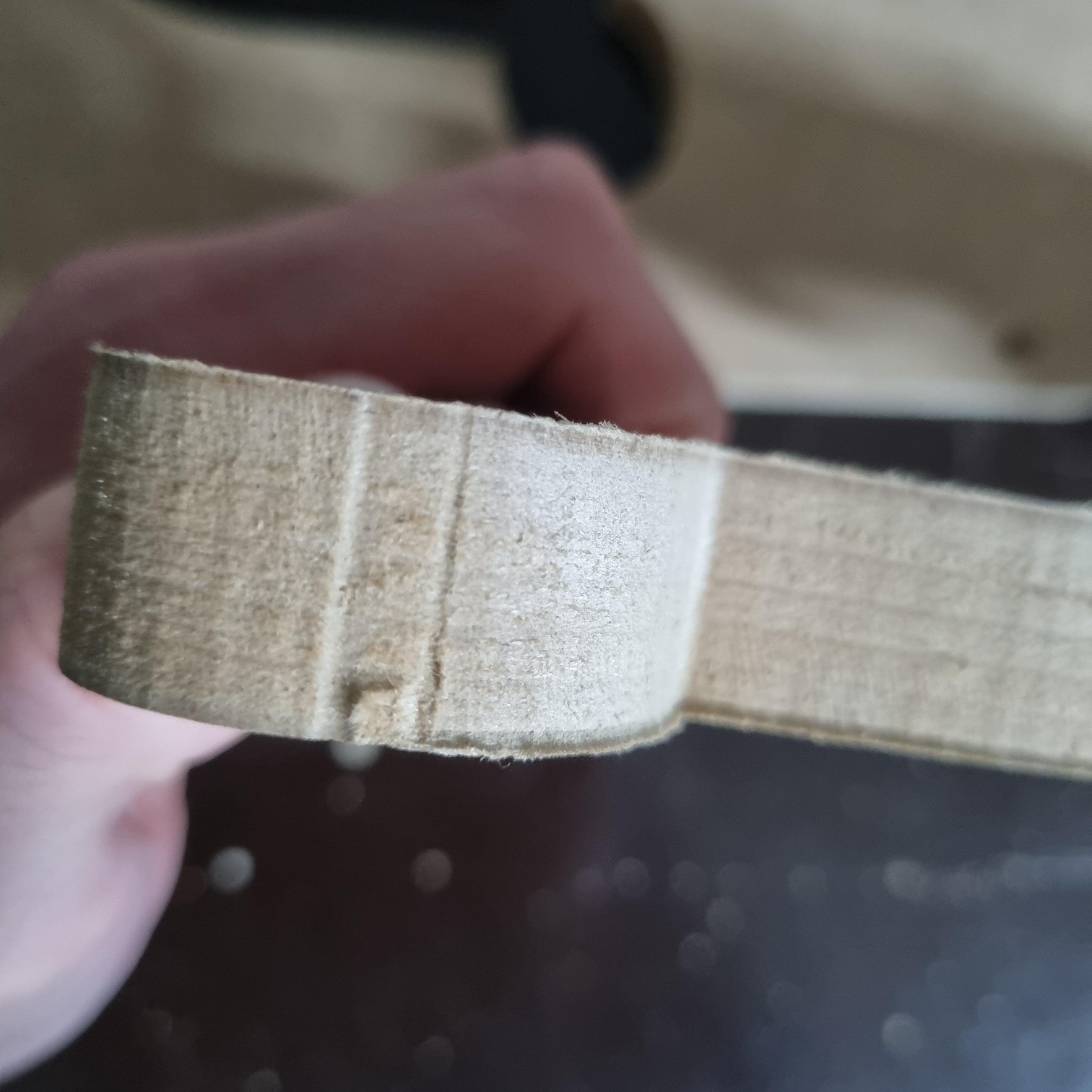
I´ve installed two alu L profiles sitting against the skatewheels.
It does indeed help with making a clean cut. However, I also seem to notice that if I run too fast, the wheels might jam. Maybe I installed them a tiny wee bit close. But that will wear out.
This is a before and after, using the exact same settings and tool.
Wonder if I would be able to get rid of the last lines caused by the finishing pass. They are barely visible, but in my quest for perfection …
As the brackets make the table unusable, I´ll probably will be looking for an alternative. But maybe I´ll try to hold on few days, as I´ve read LR3 might solve this issue too.
Is your finishing pass full depth? There should be no load on a finishing pass and you can use the whole bit to get one smooth cut.
You can’t have binding. It is a bummer you got it so close they are binding. Can you offset the screws in the other direction to let you adjust the fit? You only have to move one rail out. Alternatively, you could try to make the gantry a small amount wider.
no, I also do this in multiple passes. Tbh never tried to do this in 1x only
I often chose to do first pass in for example 2mm, finishing in 3mm.
Yes, this is what I did. During install I added 3 pieces of tape between the wheels and rail, to have some small amount of room. However there seems to be some flex after the first run, but also overnight. As the first run was ok, second one not. The same as parking it at night, and the day after.
So rolled the wheels from one side to the other, and it seems to be wearn out already, it no longer jams. So me happy
At least in estlcam, you can adjust the settings for the finishing pass to have at least your full depth (in the bit settings). In the toolpath, you set your finishing tool and the amount of material to leave (Ryan suggested 0.5mm for something soft). Estlcam will cut the roughing pass 0.5mm away from the final dimension, and use your main DOC and multiple passes. But then it will come back around with the bit down at the final dimension.
I don’t remember any other settings you need to change.
Just click on the setting for that tool you are using and you will see a more detailed settings window open. Leave the regular settings as is and adjust your finish setting to have a full depth Z, you can usually leave all the other settings the same.
In the actual tool path window just select the correct finishing tool, and stock to leave.
Thanks guys! Is there a reason why not do the first cuts in full depth then? I mean, if it could cut 18mm deep for the finishing pas it might do it for the rough cut too. Or would this put to much force on it as there’s no “guide channel” just yet?
And what distance would you suggest for harder material? More or less than 0.5mm?
Yes! The first cuts involve the whole width of the tool. The finishing pass is just a fraction of the to width.
Think of the cut as volume removrd per second. A full pass of the tool removes (for example) 3.175mm width by (again example) 3.5mm depth by 10mm per second. That is 111.125mm^3 per second. That puts a certain load against the motors and tool mount. Also evacuatig the chips from the tool is hard because it can only go above and behind the tool path.
Now say you are running a finishing pass, 13mm deep, removing .5mm material. At the same speed that’s 65mm^3 per second, obviously less load, but you also run it slower, say half speed which halves the load again. This lets everything be more accurate.