SKR pro 1.2 "TMC connection error" and funny characters on TFT

Hi guys!

Have been here quite a bit in order to setup up my MPCNC Primo. I could solve many issues but still struggle to get it work - probably because I am an absolute newbe when it comes to electrical engineering - but, thats what all you smart guys are here for, right? :slight_smile: The post might somehow overlap with a build thread, but I´d like to show you everything that I´ve done, so that you hopefully have alle the information to help me.

I created this topic with ALL the pictures but as a newbe I am allowed to only post one embedded media… will happily post the others on request.

From the V1-shop i bought:
MPCNC Printed Parts - 25mm - Primo
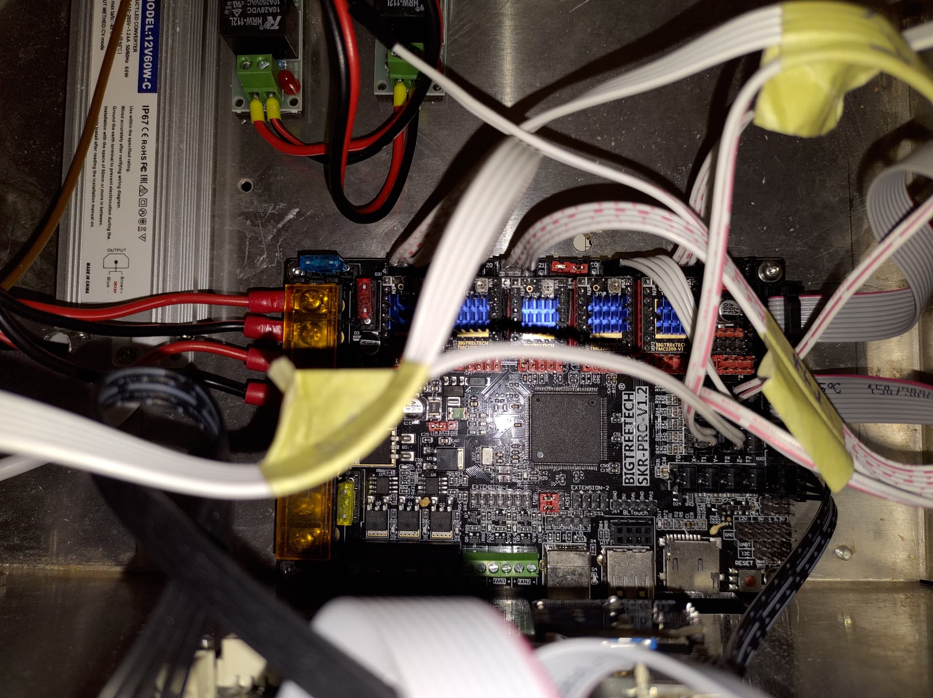
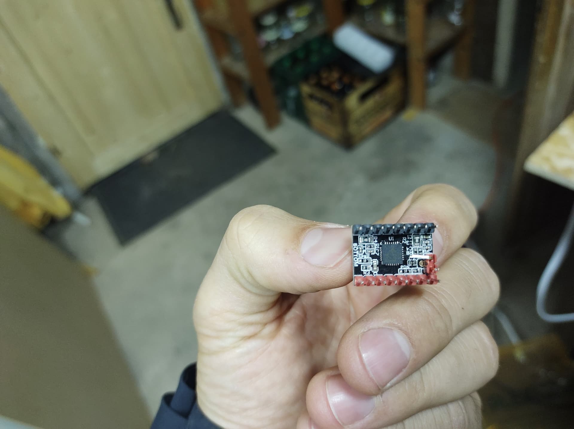
SKR Pro1.2, 5x 2209 drivers, TFT35 E3 V3 -flashed-
MPCNC Build Kit - Primo Version

The mechanical setup worked out like a charme, except, that one of the pins of one of the stepper motor cables was broken off - which I fixed by soldering a replacement to the cable (used for Z atm).

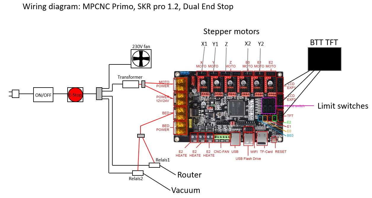
I came up with this rough wiring idea:

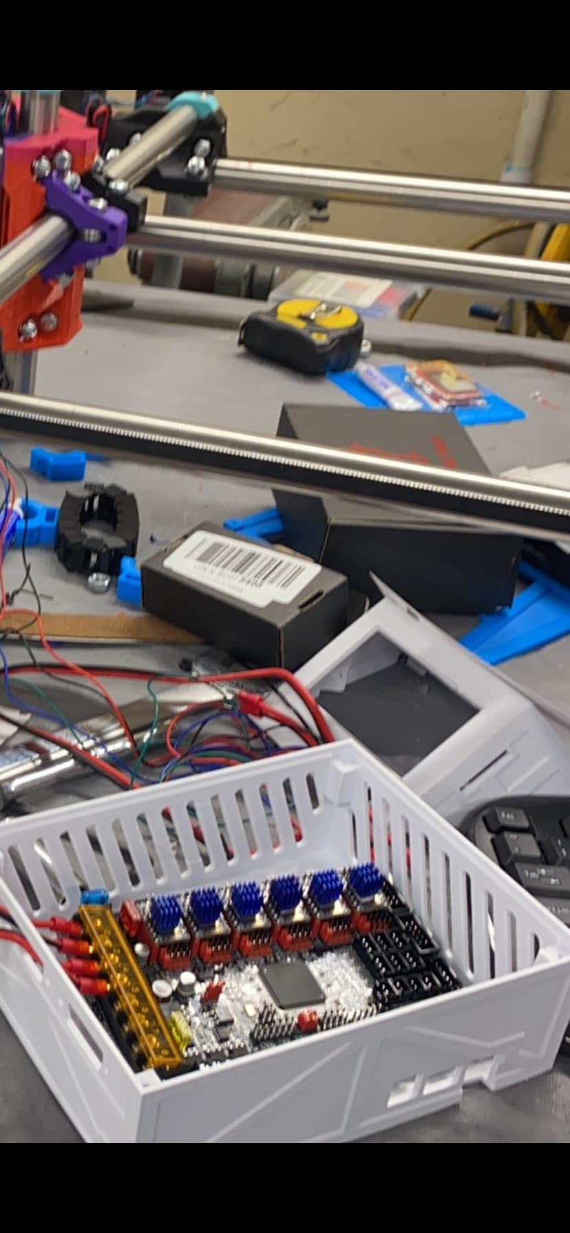
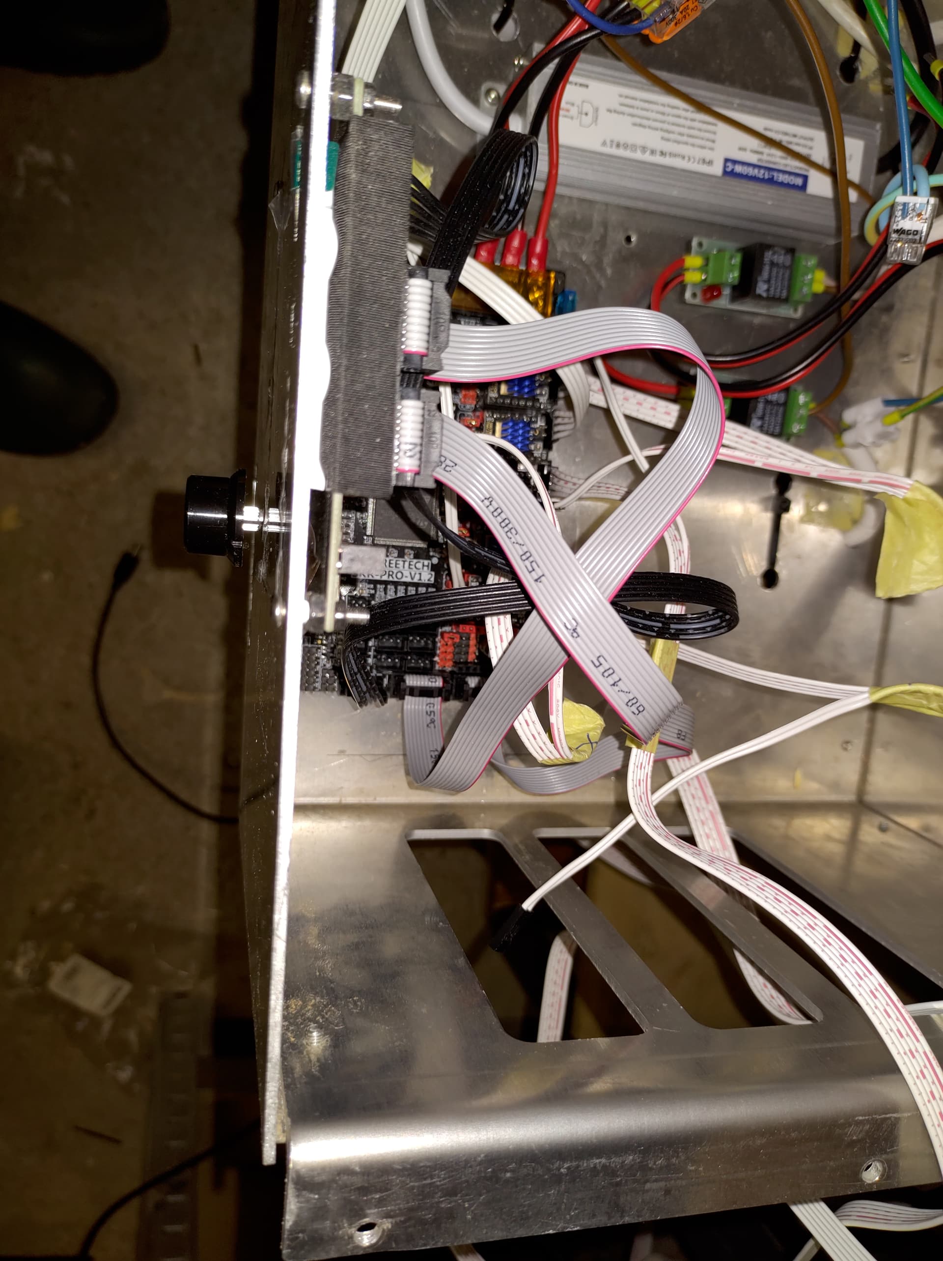
and implemented it in an alumnium box that I found on the scrap yard, that already had a working 230v fan mounted to it:

Things I additionally bought that might be important here:

  • 12v controlled 230v relais
  • Tranformer 230v to 12v, 5A:

I installed Arduino IDE with drivers and Repetier-Host, in which I changed settings according to V1 website (sorry for the German layout).

When connecting the CNC to my computer (Windows 10, 64b), I can connect to the machine in Repetier-Host but not axis movement is possible.

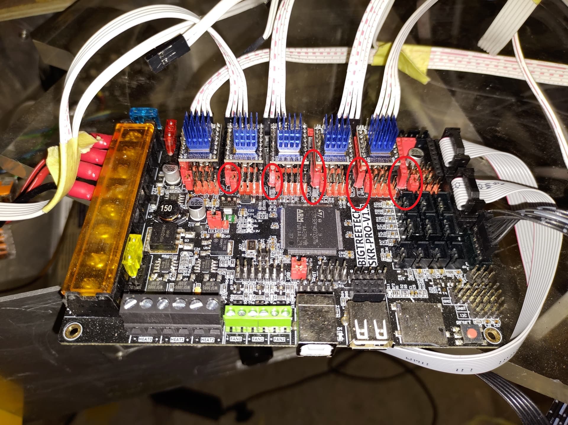
This is probably connected to a “TMC connection error” that is displayed on the TFT:

Additionally to that, the TFT creates a lot of stupid characters and is not easy to handle in Marlin mode .

This problem does not occur in Touch mode. In which I currently get an “All low” error though…

Dispite my assumption, that the correct firmware is flashed on SKR pro 1.2 board and TFT, I replaced both with current versions from V1 website (doing so I figured out, that the board will not exept micro SD cards with too much data capacity, finally worked out with a super old 2gb card)

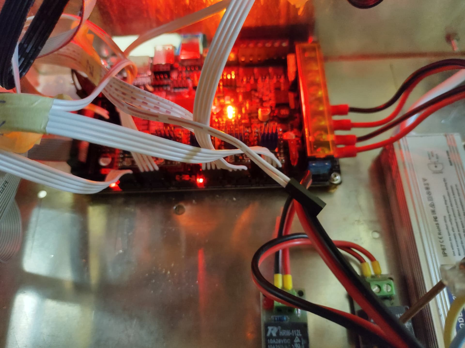
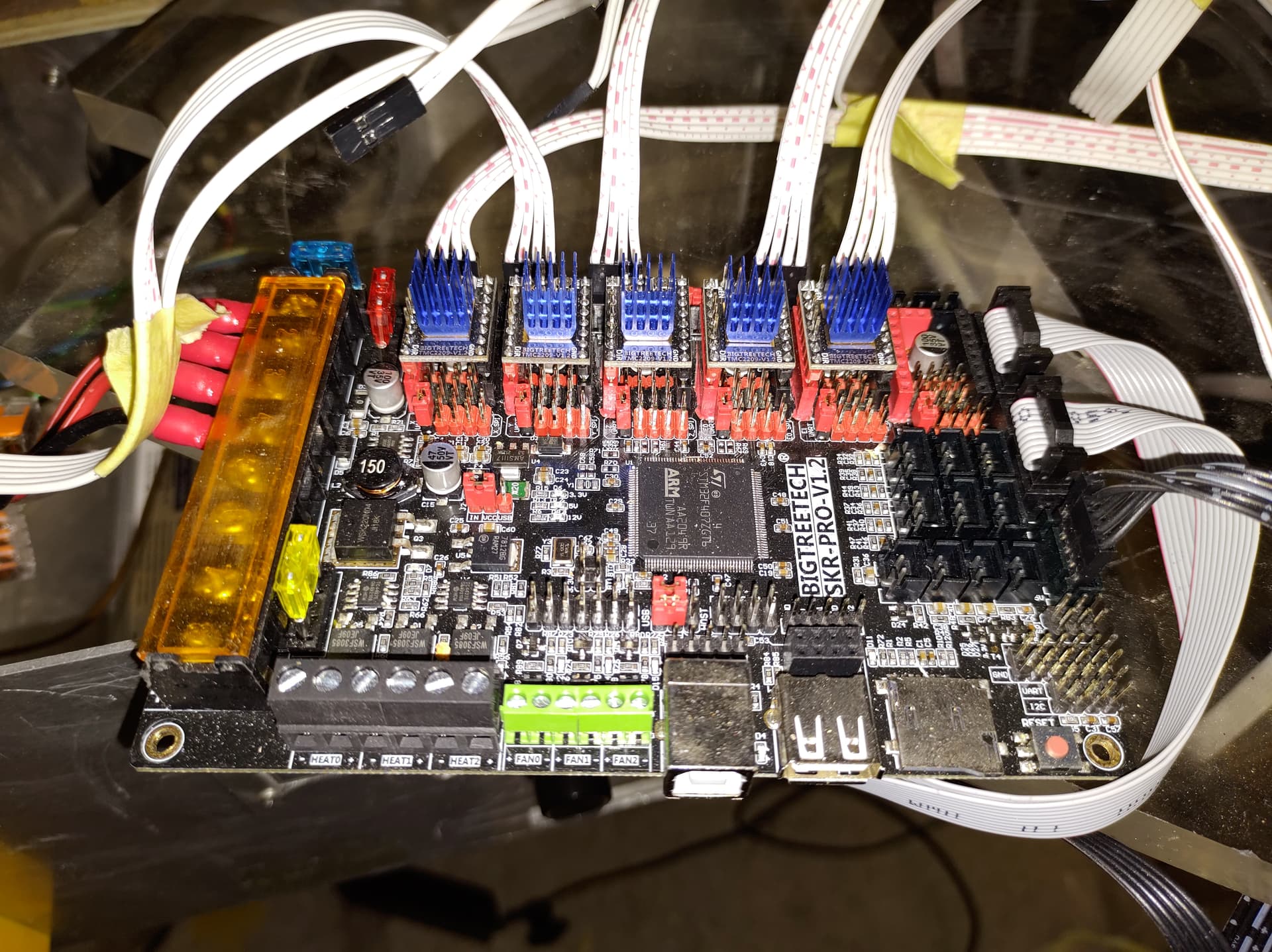
When powered up, the board looks unsuspecious for me. Centered 3 orange leds light up, limit switch indicators next to stepper motor connectors light up when I press the corresponding limit switch and the green LED next to the USB is lightning up when connected to the PC (please note that for testing, the cables to control the relais are disconnected from the “Bed” here).

My questions to you:

  1. What could be the reason for the “TMC connection error”? Did I fry one of the TMCs? Is the 12V power connection faulty?
  2. Do you have experience with this strange behaviour of the TFT in Marlin mode and is it fixable?
  3. Does it make sense to you to use the “Bed” 12v signal to control the relais’ for powering up the router and vacuum or is there a better solution for that?
  4. Which other information do you need? :smiley:

Hoping for the best - keep up the awesome work, I really enjoy this forum!
Karl

1 Like

Here´s a picture of the strange behaviour of the TFT in marlin mode:

1 Like

And a picture of the SKR pro 1.2 board, stepper motors and limit switches connected only.

1 Like

edit… NM zoomed in and can see the drivers are oriented properly.

You say you can connect to Repetier-Host… excellent. What do you get in response after sending this?

M119
M122

I believe the “all low” thing is a TMC error (usually a hardware problem), but I’m not 100% sure.

2 Likes

Hi Kev,
thanks for your reply!

heres what I get for M119:
20:10:08.725 : Reporting endstop status
20:10:08.725 : x_min: open
20:10:08.725 : x2_min: open
20:10:08.725 : y_min: open
20:10:08.725 : y2_min: open
20:10:08.725 : z_min: open

Heres what I get for M122:
20:12:14.314 : X X2 Y Y2 Z
20:12:14.314 : Address 0 0 0 0 0
20:12:14.467 : Enabled false false false false false
20:12:14.467 : Set current 900 900 900 900 900
20:12:14.568 : RMS current 1602 887 1602 1602 1602
20:12:14.652 : MAX current 2259 1251 2259 2259 2259
20:12:14.652 : Run current 28/31 28/31 28/31 28/31 28/31
20:12:14.652 : Hold current 22/31 22/31 22/31 22/31 22/31
20:12:14.737 : CS actual 0/31 22/31 0/31 0/31 0/31
20:12:14.737 : PWM scale
20:12:14.831 : vsense 0=.325 1=.18 0=.325 0=.325 0=.325
20:12:14.916 : stealthChop false false false false false
20:12:15.000 : msteps 256 16 256 256 256
20:12:15.085 : interp false true false false false
20:12:15.185 : tstep 0 max 0 0 0
20:12:15.185 : PWM thresh.
20:12:15.185 : [mm/s]
20:12:15.270 : OT prewarn false false false false false
20:12:15.270 : triggered
20:12:15.270 : OTP false false false false false
20:12:15.355 : pwm scale sum 0 25 0 0 0
20:12:15.440 : pwm scale auto 0 0 0 0 0
20:12:15.533 : pwm offset auto 0 36 0 0 0
20:12:15.618 : pwm grad auto 0 14 0 0 0
20:12:15.703 : off time 0 3 0 0 0
20:12:15.788 : blank time 16 24 16 16 16
20:12:15.788 : hysteresis
20:12:15.888 : -end -3 -1 -3 -3 -3
20:12:15.973 : -start 1 1 1 1 1
20:12:15.973 : Stallguard thrs 0 0 0 0 0
20:12:16.057 : uStep count 0 40 0 0 0
20:12:16.057 : DRVSTATUS X X2 Y Y2 Z
20:12:16.142 : sg_result 0 0 0 0 0
20:12:16.236 : stst * * * *
20:12:16.320 : olb *
20:12:16.405 : ola *
20:12:16.436 : N58 M105*26
20:12:16.506 : s2gb
20:12:16.590 : s2ga
20:12:16.675 : otpw
20:12:16.760 : ot
20:12:16.844 : 157C
20:12:16.945 : 150C
20:12:17.023 : 143C
20:12:17.108 : 120C
20:12:17.208 : s2vsa
20:12:17.293 : s2vsb
20:12:17.293 : Driver registers:
20:12:17.308 : X 0x00:00:00:00 Bad response!
20:12:17.324 : X2 0x80:16:00:C0
20:12:17.346 : Y 0x00:00:00:00 Bad response!
20:12:17.362 : Y2 0x00:00:00:00 Bad response!
20:12:17.377 : Z 0x00:00:00:00 Bad response!
20:12:17.393 : Testing X connection… Error: All LOW
20:12:17.409 : Testing X2 connection… OK
20:12:17.424 : Testing Y connection… Error: All LOW
20:12:17.447 : Testing Y2 connection… Error: All LOW
20:12:17.462 : Testing Z connection… Error: All LOW

What does it tell you? All broken except X2?

Cheers,
Karl

It means that X2 is the only driver the board is communicating with. That could mean broken drivers, but it could also be many other things as well.

The fact that marlin mode shows up garbled may be a clue. Marlin mode uses the 2 aux ports, where as touch mode uses the serial port. Are you sure you have those cables in the correct ports, not swapped around? Also, did you configure your driver jumpers exactly per the manual? Marlin mode also uses SPI, and if your motor jumpers aren’t setup right your drivers may also try to use SPI (which of course won’t work unless they are 2130 drivers).

A better photo of the board will help us see this sort of thing.

2 Likes

Idk if I should be chiming in bc I am also neewb
But did you bend the tabs back on the 2209 drivers ?
And put that single wire on the tft screen in the right spot.

1 Like

Hi Kev,
I will swap the current X2 driver with X1 and try M122 again to see whether the port or the driver causes the error.

Yes, I double, triple checked that. But now I am curios to see what happens if I swap them. Will try.

IMHO all jumpers are placed correctly.

In my understanding, only a couple of jumpers are needed.

  • The two on Z1 port
  • The ones for UART below each driver socket
  • the ones defining the power supply (12V or USB)
  • the two above the USB socket.
    Or am I mistaken here?

Please revise this hopefully sufficient picture:

Cheers,
Karl

Hi Travis,

many thanks for participating :slight_smile: Since I am a total rookie, I am sure also newbes can contribute :smiley:

I bent the pins according to the manual:

And made sure to have the single wire of the tft serial port on the other side of the 5v pin (the most upper position on the board posted one post above)

Cheers,
Karl

1 Like

As you might see, the jumper below the empty motor driver socket (E2) is also inserted. Is that necessary?

Your description of your jumper setup sounds good, and the photo matches up with it. The E2 jumper is OK but not needed; it won’t do anything without a driver plugged in.

I’m also curious what happens when you swap drivers around. Each driver talks to the mcu with it’s own serial port, but I’ve never seen a case where only one driver works like this.

The marlin mode issue may be also causing the problem with the drivers I suppose… could you also try unplugging the EXP1 and EXP2 cables and testing in touch mode again? Unplug them completely (from screen and mobo).

[edit: Oh I just noticed you have an E3 tft… you sure you have EXP1 and EXP2 ports correct?.. since the E3 does have a EXP3, a 3rd identical port, it can lead to miswiring.]

I think your driver jumpers need to be removed and one added to the far left.
Please verify. Wrote you move around as I am supper newb too and don’t want you to “let the smoke out” or hurt something.


This is how I have mine setup I will see if I can find the reference here in a sec.

https://docs.v1engineering.com/electronics/skrpro/

The uart stuff and other options I haven’t fully understood yet.

1 Like

Hi Kev, hi Travis,

thanks for these suggestions and thoughts.

I swapped the drivers so many times, here are the results:
Numbers in brackets represent yesterdays setup

Yesterdays setup:

20:12:17.393 : Testing X connection… Error: All LOW (1)
20:12:17.409 : Testing X2 connection… OK (2)
20:12:17.424 : Testing Y connection… Error: All LOW (3)
20:12:17.447 : Testing Y2 connection… Error: All LOW (4)
20:12:17.462 : Testing Z connection… Error: All LOW (5)

X2 and X1 swapped:
20:37:40.692 : Testing X connection… Error: All LOW (2)
20:37:40.708 : Testing X2 connection… Error: All LOW (1)
20:37:40.723 : Testing Y connection… Error: All LOW (3)
20:37:40.755 : Testing Y2 connection… Error: All LOW (4)
20:37:40.777 : Testing Z connection… Error: All LOW (5)

Swapped again (setup as yesterday)
20:40:59.417 : Testing X connection… OK (1)
20:40:59.417 : Testing X2 connection… OK (2)
20:40:59.449 : Testing Y connection… Error: All LOW (3)
20:40:59.464 : Testing Y2 connection… Error: All LOW (4)
20:40:59.487 : Testing Z connection… Error: All LOW (5)

Swapping X1 and Y1, as well as X2 and Y2:
21:11:02.876 : Testing X connection… OK (3)
21:11:02.907 : Testing X2 connection… Error: All LOW (4)
21:11:02.907 : Testing Y connection… OK (1)
21:11:02.929 : Testing Y2 connection… Error: All LOW (2)
21:11:02.945 : Testing Z connection… Error: All LOW (5)

Swapping X1 and Z:
21:17:22.426 : Testing X connection… Error: All LOW (5)
21:17:22.448 : Testing X2 connection… Error: All LOW (4)
21:17:22.448 : Testing Y connection… OK (1)
21:17:22.464 : Testing Y2 connection… OK (2)
21:17:22.480 : Testing Z connection… Error: All LOW (3)

Back to yesterdays setup:
21:22:49.889 : Testing X connection… OK (1)
21:22:49.905 : Testing X2 connection… Error: All LOW (2)
21:22:49.905 : Testing Y connection… OK (3)
21:22:49.921 : Testing Y2 connection… OK (4)
21:22:49.936 : Testing Z connection… Error: All LOW (5)

Unplug and re-plug of Y2 and Z:
21:25:19.564 : Testing X connection… OK (1)
21:25:19.564 : Testing X2 connection… OK (2)
21:25:19.580 : Testing Y connection… OK (3)
21:25:19.596 : Testing Y2 connection… OK (4)
21:25:19.611 : Testing Z connection… Error: All LOW (5)

Unplug and re-plug of Z:
21:26:33.106 : Testing X connection… OK (1)
21:26:33.122 : Testing X2 connection… Error: All LOW (2)
21:26:33.122 : Testing Y connection… OK (3)
21:26:33.138 : Testing Y2 connection… OK (4)
21:26:33.153 : Testing Z connection… Error: All LOW (5)

Wait for a bit, switch on again:
22:18:28.830 : Testing X connection… OK (1)
22:18:28.846 : Testing X2 connection… OK (2)
22:18:28.846 : Testing Y connection… OK (3)
22:18:28.861 : Testing Y2 connection… OK (4)
22:18:28.877 : Testing Z connection… Error: All LOW (5)

Switch off, switch on:
22:20:28.654 : Testing X connection… OK (1)
22:20:28.654 : Testing X2 connection… OK (2)
22:20:28.669 : Testing Y connection… OK (3)
22:20:28.685 : Testing Y2 connection… OK (4)
22:20:28.701 : Testing Z connection… Error: All LOW (5)

Swapping Y1 and Z:
22:22:13.807 : Testing X connection… OK (1)
22:22:13.823 : Testing X2 connection… Error: All LOW (2)
22:22:13.839 : Testing Y connection… OK (5)
22:22:13.839 : Testing Y2 connection… OK (4)
22:22:13.870 : Testing Z connection… Error: All LOW (1)

Switching back:
22:24:18.051 : Testing X connection… Error: All LOW (1)
22:24:18.067 : Testing X2 connection… Error: All LOW (2)
22:24:18.082 : Testing Y connection… OK (3)
22:24:18.082 : Testing Y2 connection… OK (4)
22:24:18.098 : Testing Z connection… OK (5)

Same driver setup, both grey serial cables disconnected form board and tft:
22:27:28.667 : Testing X connection… Error: All LOW (1)
22:27:28.698 : Testing X2 connection… Error: All LOW (2)
22:27:28.698 : Testing Y connection… OK (3)
22:27:28.713 : Testing Y2 connection… OK (4)
22:27:28.720 : Testing Z connection… OK (5)

Summarized: All driver responded in at least one port - which is good. But why do they work sometimes and somestimes not and how can I get all of them to work? I pushed 'em in correctly, each time. I am super confused.

Heres a proper picture of the board, sorry for the misleading image before Travis:

And one, showing the connection between board and tft:

Any thoughts?

Cheers and good night,
Karl

1 Like

And after swapping a bit more, this happend:
22:43:59.678 : Testing X connection… OK
22:43:59.694 : Testing X2 connection… OK
22:43:59.694 : Testing Y connection… OK
22:43:59.709 : Testing Y2 connection… OK
22:43:59.709 : Testing Z connection… OK

I carefully plugged in stepper motor and tft cables. NO TMC ERROR. The CNC moves for the first time <3 In the end, did a lot of pulling out and pushing in of the drivers do the job? Did anyone experience that before?

No Z movement so far - I gues the “repaired” pin might be the reason for that.
And the scrambled tft in Marlin mode still existent and I read from many others on reddit who share this problem with the BTT TFT 35 V3. I might buy another tft to skip this… Any recommendations?

Cheers, Karl

@kazpa, already seen this thread Screen shows gibberish and z homing only one side - #2 by azab2c ?

That photo… are those driver dupont connectors melted down to the board?

If those are melted as it looks like, take a close up picture of the opposite side of the board. This board may have crappy solder workmanship on the flip side, and if so it may explain intermittent operation.

2 Likes

By the sounds of it, maybe the pushing/pulling could have fixed whatever the problem was? We are pretty sure it’s an intermittent connection or intermittent short somewhere along the driver circuit. Could even be shorting on the aluminum box.