SKR Pro 1.2 w/ TFT 35

Hi Bob,
I tried reflashing to no avail… My board that works says: marlin 515D 2.1. 1
Machine: V1cnc 5150
Board: Bigtreetech GD_TFT35_E3_V3.1
Firm: V27.x Mar 10 2022
The new board that doesn’t work:

                                                               System:  unknown
                                                               Machine:  3D printer
                                                               Board:   Same   V3.0

Where do I change the System and the Machine description?
Can you tell me the exact MPCNC file to reflash? I also need the one to reflash the screen… I couldn’t find it on your email. With this firmware I can’t get Marlin to load but TFT loads but cycles over and over…
Rand

Just to be clear a ZIP file is a container that compress files and also can contain multiple files. For the SKR Board you do the following:

  • Go to the first link I provided
  • Find V1CNC_SkrPro_Dual_2209 on that page
  • Click on that link to download that specific firmware
  • Unzip the contents of that downloaded ZIP file. I think unzipping is built into Windows at this point. I use a separate tool, so I’m not sure.
  • There will be two files in the unzipped contents. One will be a secondary ZIP file, the other will be a “firmware.bin.” Transfer the “firmware.bin” file to an SD card.
  • With the power off, insert the SD card in the slot in the SKR Pro board.
  • Power on the board. It should flash the firmware. If successful, the file will be renamed to “firmware. cur.”

The process for the screen is similar. The link I provided in my last post for some reason is not working for me, so here it is again.

At that link you are looking for this section:

The “TFT Firmware” in red is a link to a place to download the firmware. At that link, you click on “CNC.TFT.zip” to download that ZIP file. You will be unzippling that file, and moving the files as specified by Ryan to the SD card.

With the power off, the SD card is inserted into the SD slot on the TFT display. When the TFT is powered on, the firmware should be flashed.

Note that if you are planning to flash the TFT that was not working above, I wouldn’t flash the display until you’ve successfully flashed the SKR Pro board and then had problems. I suspect the firmware on the display is just fine, and it is only the SKR Pro board that had issues.

Hi Bob,
I have tried for several days to fix these boards but still have several problems. I have followed your instructions for flashing the MPCNC bin files and understand the proper
procedure. I get the TFT screen to respond on the key pad but it doesn’t control the steppers. The Marlin boots as V1 Logo but doesn’t load any further. Any time I flash the Bin file it never changes to Cur. status. If the new Bin file isn’t loading could the bootstrap
program be corrupt? What prevents a new flash from loading?

Is it possible to copy the firmware from an existing SKR pro board and reload it onto a formatted blank SD card? I have one board that functions perfectly and want to clone it
with the same firmware. If my boards won’t load the MPCNC firmware maybe that won’t load this version also… very frustrating.

I have used the “info” screen on the TFT program to verify the firmware on each board to be sure. Is there a “G code” instruction that will give me a more accurate description of the firmware that is loaded? Is there a command that would tell me why the new firmware isn’t loading?

Thanks
Rand

I get the TFT screen to respond on the key pad but it doesn’t control the steppers.

This is what would happen if the TFT firmware is okay, but the firmware on the SKR Pro board was not working…or if they were both working but there was no communication between the two…or if they were both working and there was another issue that was preventing the steppers from moving. The baud rate for communication is 250000, so that is something to check.

Is it possible to copy the firmware from an existing SKR pro board and reload it onto a formatted blank SD card

No, and a lot of installs have been done from the version in the ZIP file, so having a bad firmware.bin file is highly unlikely to be the root of your issues.

I have used the “info” screen on the TFT program to verify the firmware on each board to be sure.

I don’t have this particular board and display, but my understanding is there is a menu item to go to a console mode. If so, send an M115 from the console and see what you get back. This g-code will not give you more information, but if you get any info back from an M115, or if you get info back from Repetier-Host if connected to the board via USB and a send of M115, it is highly likely you have working firmware on the board, and any other issues are not related to the firmware. That is, you may have a perfectly working control board and display, and the fact that your steppers are not moving may be some other issue.

If the new Bin file isn’t loading could the bootstrap program be corrupt?

We have seen instances of the bootstrap program (usually called a bootloader) being corrupt. It is very rare, so if you are having the same problem with two boards, it is extremely unlikely that the issue is the bootloader. If you need to fix the bootloader, it takes a $10 TTL board, and Jeff (active on this form) has instructions.

Just to be clear since I cannot see what you are doing, you are inserting the SD card to flash the SKR Pro in the slot on the SKR Pro board and not on the TFT? What size SD card are you using? Many of these control boards won’t read the SD card if it is too large. I cannot remember the limit, but I think it is 64GB. Many of these control boards only read SD cards formatted with FAT32. Have you tried a different SD card?

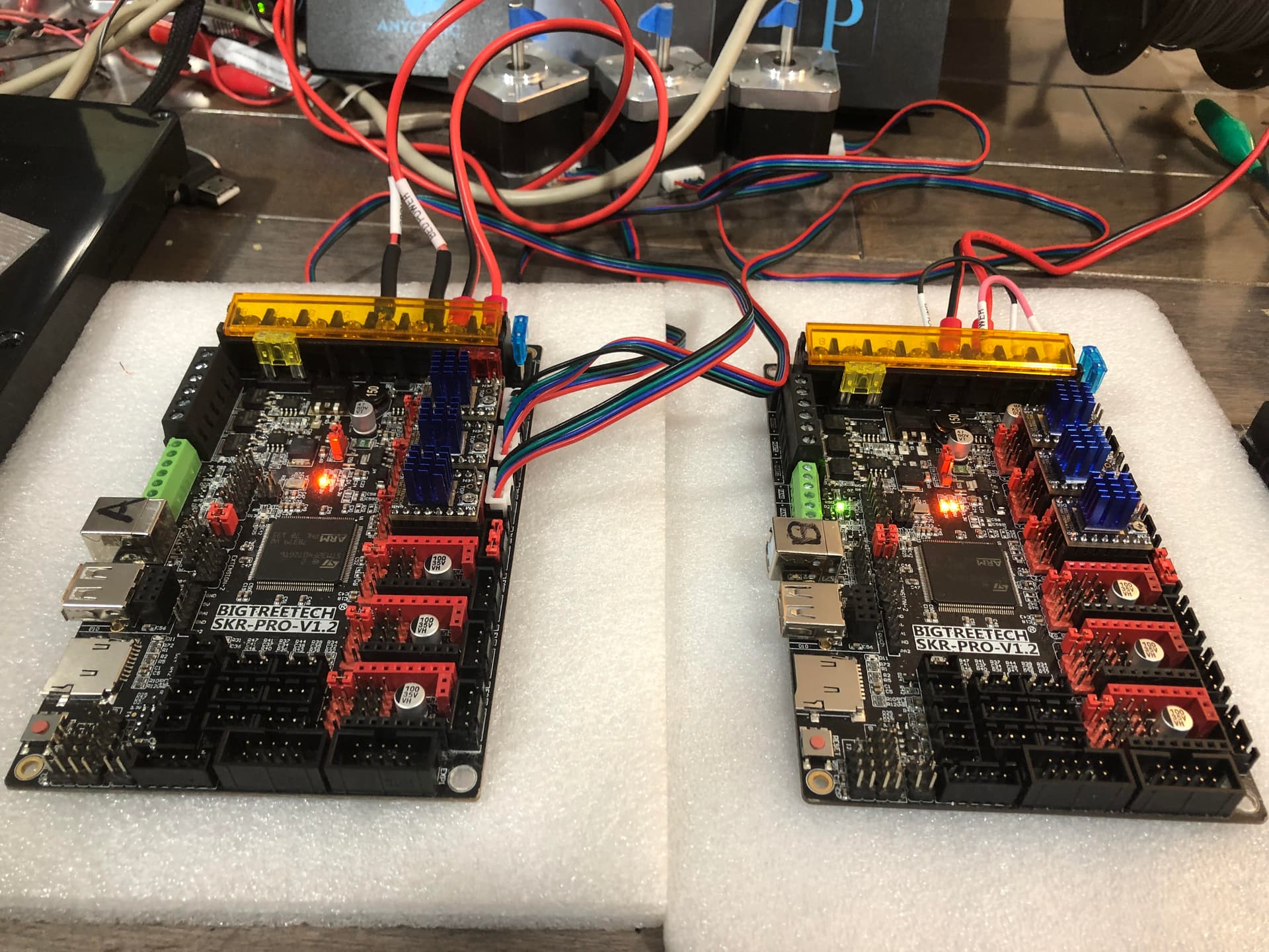
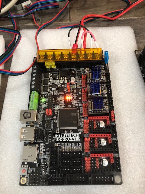
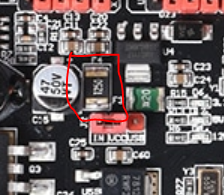
The next step is to send the M115. If you get information from either the TFT screen or from Repetier-Host, assume for now the firmware on the control board is okay, and look for another cause for your lack of movement. Take a couple of pictures of your control board and post them. Often we can spot problems from pictures.

P.S. I feel your frustration in getting this problem sorted, and applaud your perseverance in troubleshooting. It is rare to have these kinds of problems. Feel free to ask questions sooner rather than later if you are unsure about something.

Hi Bob,
It sounds like my TFT screens are okay and it’s the SKR firmware. I load the MPCNC Bin file on a Scan Disc 64GB
chip formatted to FAT32 with 4096, 8192, and 16MB as trials. Everything is set to 250000 baud. I have sent M115 through the TFT screens but do not get a response. I can’t get Repetier to connect as the port doesn’t respond when plugged into my laptop. I have tried to send pictures of the boards. Any suggestions?


IMG_2188

One issue I see is that you have the USB/VCC jumper set differently between the two boards. When set to USB, the 12V power will not power the logic of the board, which also means it would not flash itself. I think I mentioned this in a previous post. Fixing the jumper doesn’t explain everything you list, but it certainly is a concern. Start there, and rerun the M115 tests. You could also try flashing the board again.

I know you are still putting things together, but you only have three drivers installed. The dual firmware uses five drivers.

Bob,
Usually, I have both boards set with the VCC jumper set to the 24VT position. When I couldn’t get the ports to respond to my lap top I changed one jumper to USB to see if it would make a difference. It didn’t. Then I took the picture. I have tried flashing again and no change.
It doesn’t seem my firmware is having an effect on the SKR board and it is not loading. Are my SD cards set up correctly? Is the firmware from MPCNC loaded for 250000 baud?
Different subject: my machines were made 5 years ago and I wired them in series. I have more drivers but just split them between the three boards. I have been using the x, y, z, placement on the first, second, and third port on the drivers. But because I don’t get any stepper signal I haven’t noticed their positions were wrong.
If I have an older machine that is wired in series what is the exact firmware I should be loading? I would hate to think I wasted your time by selecting the wrong firmware bin. Does this firmware work with both the TFT screen and the Marlin program?

t

I have limited time right now, but wanted to get you a quick reply.

Are my SD cards set up correctly?

I believe your configuration is a supported card at a supported size. It still wouldn’t hurt to try a different card.

Is the firmware from MPCNC loaded for 250000 baud?

Yes.

If I have an older machine that is wired in series what is the exact firmware I should be loading?

The TFT firmware is the same. The SKR Pro firmware for serial is V1CNC_SkrPro_2209. Note loading the “wrong” firmware is not at the root of your issues. The dual firmware would move the steppers if everything else is wired up correctly.

I believe above you were writing about a lack of 3.3V and you were going to purchase a replacement board. Is the board that is failing the same board or the replacement? Is the 3.3V light on? When you click on Connect using Repetier-Host, does it connect to the board?

Try to format your SDCard with SD Memory Card Formatter | SD Association . Also try to use smaller card if you’ve got one as it seems the max allowed size is 32Go:

If you don’t have a smaller one you could try to partition it to reduce its size.

When well flashed the firmware.bin file is renamed to firmware.CUR on the sdcard. When flashing a green led is blinking for few seconds. If you see it blinking then when it stop remove your sdcard and check its content, if the firmware.bin file is renamed to firmware.CUR then it means the flash succeeded.

From what i learned from when i tried to flash GRBLHal on the skr pro, the sdcard bootloader will be very hard to brique if not impossible without a ST-Link, and even if it was you could still be able to access the USB bootloader with a ST-Link programmer and the STM32CubeIDE software but it would remove the SDCard bootloader if i understood it correctly.

Bob,
Should I get smaller SD cards? What size should I get? The smallest I see local is 32MB.
I format them to 12MB?
I get 3.2 volts on two boards and the other is the one I am replacing. I was going to do some more testing before I throw it out.
A major problem is connecting through the USB cable the port is not recognized when I plug it in and therefore Ponterface or Repetier will not connect. I can’t test the G code commands you have given me until I fix this. Tomorrow I’ll set up another computer and load Repetier Host and test the connection process… I have been using a new laptop and it should work but I’ll try to get the answer by trying the different machine. Could it be the UBS cable? I have been putting the SD chip directly in the SKR board with the grey cables unplugged. It doesn’t change from BIN to CUR… that wouldn’t affect the flashing of the firmware? The cable shouldn’t make a difference just the reporting…

1 Like

I will get some smaller SD chips tomorrow. I think I can get 32MB chips. I have been formatting them to FAT32 and 12MB partitioning. I am flashing firmware from MPCNC
as a bin file. It doesn’t change to Cur when I flash it in the SKR. wait for green leds. take chip out and read it in the laptop to see if the file type has changed. Something is keeping it from being flashed?? Is there another firmware bin file I can load through the USB connection through the SKR board to test?

Just in case, here is resource links for repairing the bootloader:

I was wrong in my last post, SDCard bootloader can be restored with that rescue…

But first try with your smaller card to come and do not format it with OS format tool but with : SD Memory Card Formatter for Windows/Mac | SD Association

1 Like

Bob,
Today’s update:
Board A - three yellow leds
no green led
6 red driver leds
It’s powered with 24vt both circuits
When I connect the EXP1 cable the screen comes on but the 3vt led dims or flashes and the red driver leds go off and on. The screen boots and then reboots time and time again… It’s as though the chip is loading but doesn’t finish and starts over and again.
The screen goes into Touch mode but doesn’t control the drivers. The Marlin mode doesn’t boot and the touch mode takes over. The green led never lights. I have tried to flash the SKR board many times without no success.

Board B: two yellow leds
one green led
no red driver leds at all
Powered by 24 vt both circuits
Only two yellow leds are on and the green led is on and none of the red leds are on.
When I plug in the black cabel the screen comes on and responds to keypad but the drivers have no movement, if I plug in the grey cables the EXP1 wire gives it power and shows the Marlin mode but doesn’t respond at all… this is the board I can’t get 3 volts and don’t know if it can be saved? My guess without the 3volts it won’t flash?

Any suggestions would be appreciated…
Rand

Well, the green LED means that a dan has been turned on. The red “driver” LEDs mean that the endstop pullup resistors are enabled.

If Marlin mode comes up, then the firmware is loaded. The board where you do not get Marlin mode, the touchscreen interface is a red herring. You will get touchscreen mode if you just give the screen power, it has its own processor to drive that. The TFT35 is its own little computer in touchscreen mode, but in Marlin mode, it depends on the control board firmware, so you get no display if the firmware isn’t there.

Have you tried a different power supply? The one that keeps rebooting could be from a bad PSU. I had one issue that I misdiagnosed because the PSU had 24V, but dropped to less than 5V under load, resultimg in the board crashing as soon as I turned on a fan (which the firmware did during boot)

The CPU runs on the 3V3 power, so no, it won’t flash, or run the firmware either.

I didn’t completely understand during your last post. You have two boards, and both are not working? Wow, you are really getting hit by something that is usually plug and play.

When I connect the EXP1 cable the screen comes on but the 3vt led dims or flashes and the red driver leds go off and on.

This is a strong indication that something associated with that cable is shorting VCC to ground. Bent pins are a common reason for this to happen, and since you are having trouble with both boards, the connection between the cable and the display or the cable itself are the most likely culprits. If you cannot find any bent pins, I would take a multi-meter and check to make sure none of the wires in the cable are shorted.

Note that a short like this would explain just about everything you’ve experienced. And it does mean that the board without 3.3V probably has a blown fuse or a blow voltage regulator and will take replacing components to get it working again.

If you unplug everything, including the stepper drivers, will this new board flash the firmware from the SD card?

Thanks Bob,
Tonight - I am going to take the screens apart ( I have three) and test the black cable and the grey cables and look for bent pins. Then I will change to a new power supply and reconnect all three boards and try them again. I do get the sound of the fan going on and off on the existing power supply when it cycles. Maybe it is faulty and causing all the software problems? If I replace the power supply is there any reason it would correct the 3vt problem or is the board without the power led fried for good? If I put my meter on the output of the old power supply would I see the fluctuations without a load? Is it worth checking or just move on and trash it? Where is the 3vt fuse on the SKR board? If I short over it will the board operate?
I still have a problem loading the basic MPCNC V1 Bin file thru the SD chip. If I correct the voltage problem on the SKR should these be plug and play? I have loaded bunches of Mega Arduino Ramp boards with V1 firmware that I have loaded earlier and these SKR boards act differently. I am doing something wrong this time…
Rand

Dan,
Can you explain this?
What is a dan? I understand the red leds = I don’t have the endstops connected yet to avoid confusion.
Rand

Typo

He meant fan

1 Like

Thanks Neil - I don’t have a fan connected to this board. Is this called out by the firmware by V1 MPCNC? Does the led light to say there is power available or that there is a load (or short) on the fan terminal PC8 ? My other board doesn’t have a fan either and the led is off. Why would they be different?
Rand

If I replace the power supply is there any reason it would correct the 3vt problem or is the board without the power led fried for good?

I cannot think of a reason a new power supply would fix the 3.3V problem.

If I put my meter on the output of the old power supply would I see the fluctuations without a load?

I’m only a hobbyist with electronics. It is worth checking your power supply with a meter, but it is possible for the power to have problems that won’t tell with just a meter. If a bad supply seems to be working (i.e. not just completely dead), often the issues only happen under load.

I still have a problem loading the basic MPCNC V1 Bin file thru the SD chip.

Just to be clear, you tried with everything unplugged? And you’ve tried with more than one SD card with the board in that configuration? If so, then I would lean towards that board having a bad bootloader. In the couple of cases on the forum, I’ve not seen any indication of why the rare board loses its bootloader.

If I correct the voltage problem on the SKR should these be plug and play?

For most people, these boards are simpler to program than a Ramps board. We have seen a few board failures on the Forum, including losing the bootloader, but it is rare for anyone to have any trouble with SKR Pro. And, if I understand correctly, you have two failed boards. The chance of that happening without there being some sort of connection is very low. Note that voltage as a source of the problem is only a guess. It is possible the issue is elsewhere.

Where is the 3vt fuse on the SKR board? If I short over it will the board operate?

You would need to do some careful analysis to figure out where to short. There appear to be two fuses on a single SDM chip. The chip is adjacent to the VCC/USB jumper, and you should see F3 and F4 labeled next to the chip.

image

And it is possible the issue is not the fuse, but something else like the 3.3V voltage regular.