Skr pro v1.2 control for spindle and laser

Well I’ve been reading the most recent laser threads and the earlier spindle control threads and well there is a vast amount of information there but there doesn’t seem to be anything that sums it.

I just bought a 500w spindle with Mach 3 style 0-10v speed control. Hoping to set that up but worry choices made will compromise a laser.

I also hope to setup a laser at some point and was following @vicious1s detailed testing and configurations but I stopped reading for a few days and there was something about new firmware and waiting - but I don’t know if that happened or which of the 3 recommend ways of doing spindle is best. I liked inline speed control but got lost if that compromised spindle control.

Further I would like to setup maybe airblast or some other GCode controlled “coolant” for either milling or laser or both.

When I look at the skr pro with the 3 pwm fans, the pwm pin they were using for the laser control and the heater ports (not sure if they are pwm) it seems like there are enough IOs to get this done.

I’m willing to help document if there are working configurations. Or is this a case where it is close but the software is not there yet? If that’s the case maybe this can be a forward looking spec to code to.

Sorry it seems things are all over the map right now am I wrong? How can we align on a solution? We have a 32bit board with processing power, storage and IOs but there doesn’t seem to be a spec for how to build a complete solution after you get things moving and spinning.

Thanks for reading this far. Thoughts?
1 Like

Ryan’s tests are in main, but we haven’t made a release. Waiting on another thing ATM. You can try grabbing a nightly build. Those are in the actions tab at MarlinBuilder releases.

Turning on a fan to control coolant doesn’t need a firmware change M106/M107 should work already. But whatever it is will work better if it is 12V. Otherwise, you’ll need to wire a relay or buy the iotrelay.

1 Like

The funny thing is, buying those things is putting dollars into pockets. But very few people pay anything to Marlin for the software. Which is, in some ways, more complicated and specific to what we need. It is amazing anything works, really.

1 Like

I’ll agree with that. The software is what makes it happen. In the 35 years I’ve done software, starting in ECAD and ending in managing IT department, software has gone from $1000s per user to giving it away. Now that I’m on the receiving end I’m trying to contribute back - why I’m doing the PP for F360.

That said, feels like if we could define a target we could find the mass to make the software changes to hit the goal. I do realize some of these problems are not an hours work but days of engineering - something unpaid devs just can’t do (though many still do - kudos).

2 Likes

I am using a 500W spindle with Mach 3 style 0-10v controller and FINALLY have it all working.

Spindle control through RAMPS board was the hardest nut for me to crack in my MPCNC project.

I saw this post many times in my searches but eventually tracked down a few things that may help others.

I am using two RAMPS boards, 1.4 and 1.6. I discovered that the V1Engineering dual endstop (and also default Marlin code) use pin 4 to PWM control the spindle speed. On my RAMPS boards that is the SECOND set of servo pins from the Reset button.

But I also discovered that alone was not enough.

You also have to enable it in the firmware. Spindle control is disabled by default. This involves uncommenting the line #define SPINDLE_FEATURE in Configuration_adv.h in Marlin 2.0.7.x

And once I was there I saw there was 3 ways to specify the spindle speed…
PWM255 (the default, using M3 S0 through M3 S255 to set from off to full)
PERCENT (using M3 S0 through M3 S100 to set from off to full)
RPM (using M3 S0 through M3 S50000) to set from off to full…)

I opted for RPM since that looked like the obvious… and nothing worked… went back to PWM255 and worked fine so I set my tools to use RPM from 0 to 255 (lazy fix) until I could figure it out…

Well another day of debugging and I did figure it out… its a bug in marlin in 8 bit controllers as far as I can tell. In src>>features>>spindle_laser.h there is a section called class SpindleLaser and in there the following line has an issue:

return unitPower ? round(100 * (cpwr - SPEED_POWER_FLOOR) / (SPEED_POWER_MAX - SPEED_POWER_FLOOR)) : 0;

I found a reference on the Marlin github to the following change that worked for me… its just adding the float (as I commented):

return unitPower ? round(100 * float(cpwr - SPEED_POWER_FLOOR) / (SPEED_POWER_MAX - SPEED_POWER_FLOOR)) : 0; //TJ added float

So that gets you a PWM signal at a known pin on a RAMPS board… The next is to turn that into a 0-10v signal for the controller.

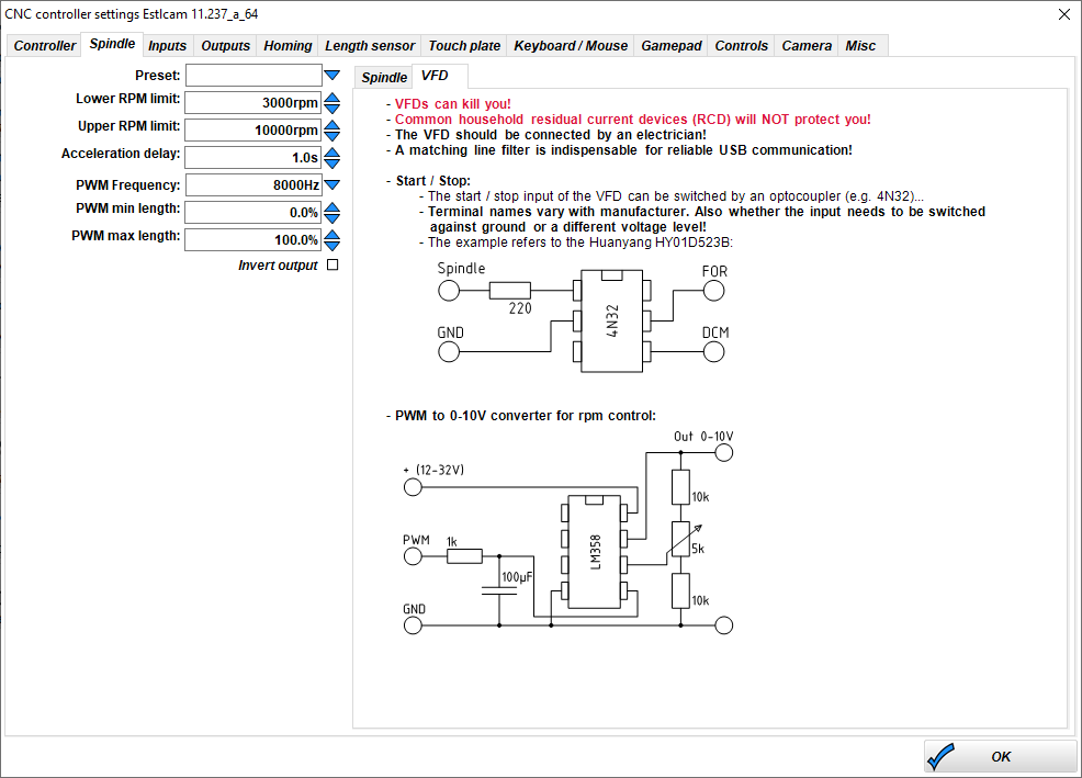
I stumbled across this helpful bit in ESTLCAM

The lower image is exactly what I needed. It is an LM358 dual op amp (only one half used) that takes the PWM signal from pin 4 and uses the 1K resistor and 100uf capacitor to provide a nice smooth 0-5V signal from the PWM signal out of the controller. Then the variable resistor (potentiometer or pot) lets you adjust the gain so that with 5V input you get 10V output.

Hope that saves others the same grief I suffered.

4 Likes

2d

Further on this… may be issues…

I started having random milling errors. It would random detour… so far the way I have resolved these is to disable the spindle control. My current working theory is that spindle control is probably fine IF you are using PWM255 mode on an 8 bit RAMPS/mega256 setup but the RPM mode may be causing corruption elsewhere even thought RPM seems to be working… So for now I would hold off on the RPM fix and use PWM255 until I confirm.