This post is more of a heads up for anyone else trying to do what I’m doing.
TLDR; use the laser controls in Marlin mode not BTT/Touch mode on the TFT…
I’m trying to hook up this TTL controlled laser. The laser has it’s own power supply and just needs a PWM signal from somewhere. It wants 3.3v-12v on the PWM. The current 509 firmware has a laser control mode. This should be easy right?!?!?
Yes it is… HOWEVER…
I just burned about 5 hours trying to get PWM out of PC9 in the firmware. Fixing my platform.io install (i broke it doing something totally unrelated) and rebuilding Ryan’s firmware. Rebuild the TFT firmware Broke out the scope on the PWM lines. Can’t get it to work… Turns out the laser control mode in the TFT (not in the SKR) only doinks with the fanspeed even in laser mode. It’s just wiggles the ground on the fan. If you go back to Marlin mode and use the laser controls from there, everything “just works”.
No practical knowledge, but from reading in the forum, this is my take away. Traditionally, the laser has been controlled using the fan pin and M106 and M107 g-codes. Recently laser support was worked on in Marlin, and Ryan enabled laser support in some of the versions the V1 supported firmware including the Rambo and the SKR Pro versions. This support controls the laser with the ‘S’ parameter of the G0 and G1 g-code commands as well as M3 and M4 g-codes. The TFT is still generating the older, M106 and M107 g-codes. So which controls (Marlin or TFT) will turn on your laser will depend on how you setup your laser…if you connected it to a fan pin or the defined laser pin.
Thanks @pbostley! I tested this this morning, and it works great in Marlin mode. I would have probably spent a lot of time trying to figure this out if it wasn’t for this post.
I vaguely remember a laser mode in the settings, but I just checked and it just changes the icons and text, not the commands. I should make that do M3/M5 when in laser mode and M106/M107 in fan mode. WDYT, @dart1280?
@jeffeb3 There is the basic problem with using the fan MoSFET to control laser PWM of modulating the wrong leg (modulating the ground), for this reason alone I would suggest you are better off using M3/4/5 and assigning a PWM capable pin for laser control. So yes Jeff, your suggestion would seem to me to be sensible.
@dart1280 For the old style diode emmiter: Electrically, modulating the ground is fine. So long as the emitter is insulated it will stay at your drive voltage, and current will flow when the ground is enabled. This is a pretty common way to hook up industrial automation devices.
modulating the drive voltage requires that the switching mosfet be electrically isolated so it’s gate can be around a source voltage at Vcc instead of around a ground. It’s much more expensive to build that way.
Except that you are not just driving an old style diode emitter, you are driving the regulator IC, not the diode directly and you usually have no idea what that chip is as the numbers are commonly erased from the unit. It is fair to say the control electronics is expecting a positive going PWM signal. It may work, pulsing the ground, but you are driving the device out of spec.
Sending G0 Sxxx will only work after sending the laser on command (and having a move rate set) , so you still need either M106 or M3/4 somewhere in the command chain before the laser will actually fire. G0 also doesn’t work in GRBL, it has to be a G1 move command.
I flashed the tft firmware successfully then tried to update the firmware on the skrpro 1.2 in the tft sd port and got an illegal flash error. Now I can’t get the tft back with the same firmware. How do I get it back?
The goal is to get my creality laser working. If this firmware only works on the 5v port then is there any way to get this working in the fan0 port?
Can’t help with your query but you are using the wrong firmware I think, there’s a separate release for the Turbo board, the one you have mentioned is for the SKR PRO.
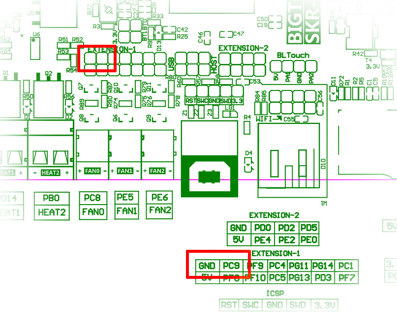
I don’t have the SKR Pro, but I’ve been following the laser topics carefully. If you are running the current version of the V1 maintained marlin firmware, then laser control is enabled. V1 defines the laser pin as PC9. If you want to change it for some reason, it is defined at the top of configuration.h. The PC9 pin is on Extension-1 at the middle bottom of the pinout diagram. That section is called out here with the ground connection and PC9 highlighted in red:
It is really plug and play. The four wire connector goes to the laser, the provided power supply plugs in, and the yellow and black pair go to your control board and use PC9 and ground.
As for controlling/testing it once installed, I’m told that the laser items on the TFT menu in the V1 maintained firmware work. It should also work using the laser items in Marlin mode. It will respond to inline commands, so you can send the following g-code:
G1 X1 S255
S values are in the range of 0 to 255, were 255 will be full power. You can also set the pin directly with something like this:
M42 PPC9 S255
And finally saw one report where M3 is also enabled, so this may also work:
M3 S255
Personally, I’d put a voltmeter on the pin and test the methods of turning the pin on before I attached the laser.
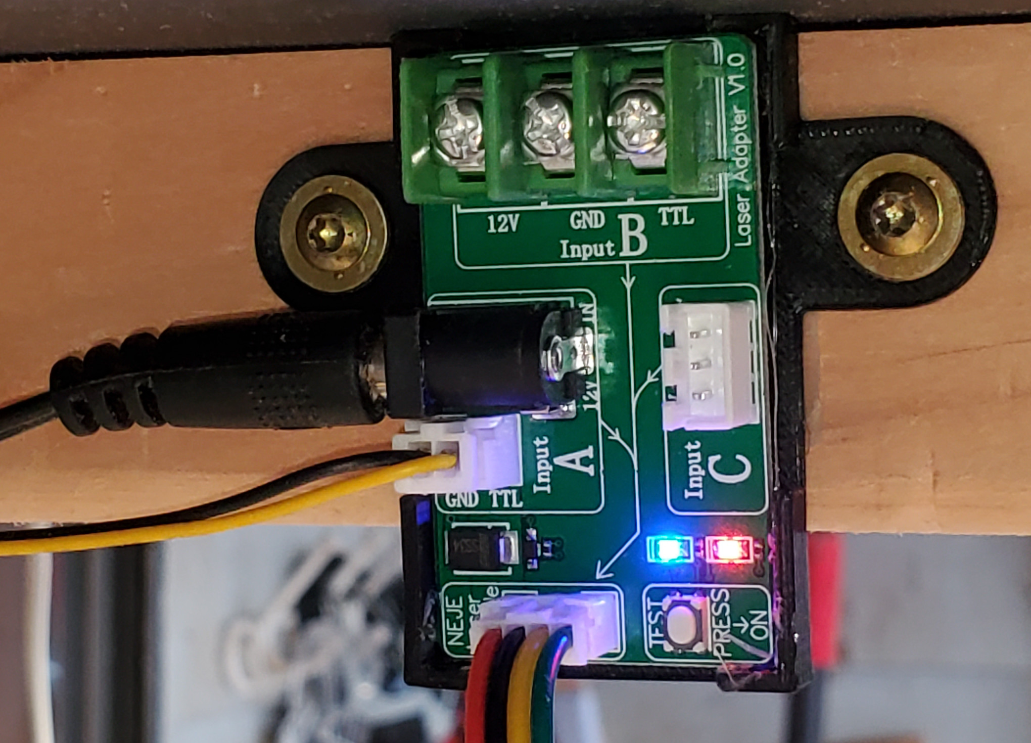
I ended up using GND, PC9(as PWM), and PF9 (as power on/off).
I have 2 lasers an NEJE and another that was supposed to be more powerful but was a scam (claimed 7.5w output, but is way less).
The NEJE is a much easier to use, easier to get right, and decent laser.
Which wire did you plug up to the PF9 pin? Are you using the control board that came with the laser, or did you hook it up directly? Did you have to change anything in Marlin for the PF9 pin? I looked through the v1 Marlin firmware and didn’t see PF9 defined as anything (but I’m also new at custom compiling Marlin, so I might not be looking in the right place).
I’ll post a diagram later, but I use PF9 to trigger a SSR for the +12v. That way “SPINDLE_LASER_ENA_PIN” functions as an actual power off/on for the laser.
Do you think it’s possible to use one of the fan pins for power, instead of PF9 and a SSR? I’ve seen another post where someone used FAN 0 for the 12v, and then I’m guessing issued fan speed commands to control laser strength. From what I’ve read, PC9 controlling PWM gives better results, but I was thinking, maybe you could just set FAN 0 to 100% to turn it on and power it and then use PWM on PC9 to control laser strength, either by defining SPINDLE_LASER_ENA_PIN to FAN 0 (not sure if the firmware will let you do that) or you could just issue M106 at the beginning of your gcode, and M107 at the end to turn the laser on and off.
I picked up the Neje 40w for my lowrider, but haven’t had time yet to try and set it up. I already have way too much stuff strapped to my Y plate, so I’m hoping I can figure out a setup that doesn’t require adding another power supply, a control board and a SSR. Unless someone already knows what I described won’t work, I’ll probably give it a try next week sometime when I have a few hours to tinker.