Slightly crazy idea to obtain very high precision

Today I was thinking about a way to obtain precision in the range of 0.01-0.02mm (0.0005" to 0.001") while taking as many sources of inaccuracy into account as possible. That includes skewness, belt stretch, skipping steps, etc.

I thought about delta 3d printers (like a Kossel, Rostock, etc). There are three towers. Each has a carriage that is moved up and down by a stepper. Together they position the extruder at any point in 3 dimensions. Then I thought, what if I could do the reverse? Attach the ends of the arms (that normally hold the extruder) to the router. By moving the router, the arms will move up and down. If you replace the steppers with rotary encoders, you can measure the position of each of the carriages, and then compute the exact position of the router in 3 dimensions.

The towers would have to be pretty far apart and pretty tall probably. Everything would have to be built really accurately. So it’s probably not feasible to build it exactly like a reverse delta printer.

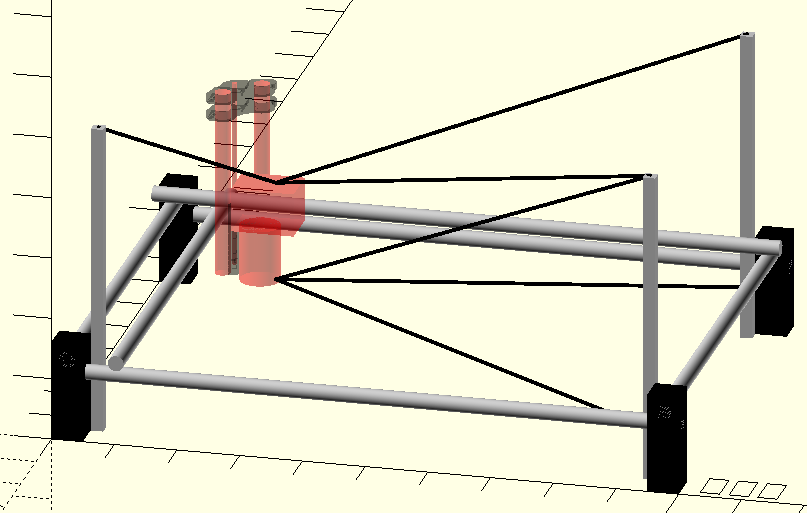
So then I thought, what if I attach a GT2 belt to the router, and attach the other end to a tape-measure-like spring loaded pulley and put the rotary encoder on the belt close to that pulley? When the router moves, the belt rolls up and unrolls as needed. The encoder measures the distance from itself to the router. Put three such belts on the router and you can measure in 3D.

This system works like a closed-loop stepper system. But it has the advantage that it can be completely independent from the MPCNC (or whatever you attach it to). It is not affected by sideways force on the end mill. Belt stretch doesn’t affect it (aside from a slight stretch in the measurement belt, but the tape measure would hold it at a similar tension at all times). Frame and gantry non-squareness are automatically corrected for.

If you have a aluminum block of known dimensions, you can probe it and that would allow you to accurately convert the measurement system’s orientation to your workspace orientation.

One thing this system would not “see” is tilt of the gantry (and therefore end mill) due to sideways forces.

What do you guys think? Is there any merit to the idea? Any obvious problems I have overlooked?

1 Like
  1. The software ask is pretty big. You’d need to really dig into the controller firmware to read those inputs (quickly) and compute offsets to counter the error. The speed of the corrections is going to really affect the accuracy. You’d certainly make your life easier by picking something that is more flexible than an 8-bit board.

  2. How do you set up the measurement devices more accurately than the machine? How much less work is it to do that than making the machine more rigid?

  3. Is the position error really the source of error that often? Once you start skipping steps, that error is crap, but up until that point, it’s actually quite good. I would guess it’s at least the same order of magnitude as the GT2 based measurement system.

It’s an interesting idea though. You can get by with 2 distance measurements if you’re only interested in XY. I think Z is going to be very noisy when the measurements are at oblique angles (GPS altitude is much worse than lat/lon).

3 Likes

You still have spindle, collet, and endmill wobble, run out, and flex as well. Ultra precision is not always done completely by CNC, typically you will get finishing operations by hand, special tools and one task specific machines. CNC can be this accurate but typically you only need one aspect of your design to be that precise ($$$expensive$$$). Think engine blocks, super high tech fancy ones get milled by some of the worlds best CNC’s and they still get honed to spec, bearing journals then ground, decked, and surface lapped. Getting close is awesome getting “ultra close” is a whole different animal in every aspect, machine, CAM, tools, spindle, humidity, room temp, endmill age/wear.

If you needed something to be better than usual you can make your part, leave it attached, take a measurement, make adjustments in CAM, run another finishing pass. once you understand the nuances of your build that trial and error can be almost non-existant, you will know how much to leave or how many passes to take.

5 Likes

I like this idea and I had actually thought of something similar. Ever since forever, the name of the game has been open loop control and high stiffness. Going to low-ish stiffness with closed loop control can potentially have good accuracy, although there might be certain problems you may still encounter like chatter or other dynamic behavior that is too fast for the servo to correct.

I did not find any “digital tape measures” I could buy so I began building one. I found cheap $2 tape measures at Walmart which were nice for the coil springs inside. Alas, I got distracted by this MPCNC thing so it got stalled indefinitely but I am still interested.

I was thinking an ODrive controller would be a good low-cost servo, using a PID within a PID, where the inner loop is the motor position and the outer loop is the digital tape measure matching its target.

I haven’t thought it through completely, and these are the high level concepts. I think it would be fun to see this go further but I have too many other things so I dont know when I will be able to continue.

2 Likes

Yes. I was hoping that Marlin would have support for closed loop steppers, but it appears it doesn’t. I’m thinking about using a Teensy 3.5 (120 MHz 32 bit ARM cpu) to read the signals from the encoders and tell Marlin the actual position. Or, hook up the stepper drivers to the Teensy as well, intercept the step/dir signal from Marlin, and then command the stepper with the Teensy. Low latency and accurate timing is going to be key though.

The tape measure pulleys would be fixed in position (aside from being able to swivel around to follow the movement direction of the belt). You’d need to know the exact distance between them. I think that’s all. (In contrast to the reverse-delta idea, where there are a lot of parameters you’d need to know). Three (non-colinear) points always form a plane. Make sure the router always stays on one side of that plane. Pick a point on that plane as your origin, and the coordinate system is fully defined. Now, use a probe to find the workspace coordinate system. You can then translate back and forth between the two.

Making the machine much more rigid would cost lots of money. If my idea works, you can built it for $50-$100 depending on the components you pick. Like Jamie, I’d like to see how far I can go with low-ish stiffness using a closed-loop solution.

Very good point. I’m not sure. I do know that squareness can be a lot better than what you can measure manually. I also know that belt stretch is real, especially on bigger machines. Perhaps the light load of a finishing pass makes it less of an issue.

Skipping steps is not my main concern, but it would be nice to catch issues like I had with my Z axis falling 20mm. It would be best to just kill the job automatically (and remember how far it got so you can restart later). It would make me feel a lot safer.

Also, a moving stepper is always lagging the ideal angle. The more torque it needs to use, the larger the lag angle. If the lag angle gets too big it “jumps” to the next full step and that’s what skipping a step is. Skipping shouldn’t happen, but the lag angle will definitely vary depending on the load. One 1/32 microstep with a 1.8 degree stepper and 16T pulley is 0.005mm. If it can lag up to 16 microsteps before skipping, that would mean max 0.08mm of lag before a skip. It’s a small effect, but lots of small effects add up.

I’m thinking of two possibilities: 1) Mount each tape measure in a different corner of the MPCNC but at a decent height above the workspace. Or, 2) mount two in adjacent corners more or less at workspace height and mount the third high above the center of the workspace. I think I’ll try option 1 first.

That’s the kind of real-world experience and knowledge I’m missing :slight_smile:

I saw a video on youtube from NYCNC where he visited Kern in Germany. They said “at our tolerances, steel starts to behave like putty” or something like that. I’m not aiming for that level of accuracy where I need a climate controlled room etc. I’d just like to see how close I can get with low-ish stiffness. Maybe the answer is “not any closer than before”.

That’s a good idea. But doesn’t this only work when you have very good positional accuracy and the left over inaccuracy is mostly due to the factors you mentioned above? I mean, you might get one or two measurements spot on, but not the whole part if your gantry isn’t square for example.

1 Like

I like this idea too. You’re still operating closed loop, it’s just what you’re closing the loop around is different. Like a sculptor doesn’t maintain precise programmed position of the hands and chisel per se, but closes the loop around the desired shape of the workpiece. Or people who grind 8 inch telescope mirrors with their bare hands for God’s sake.

Either way, your ability to be precise hinges on your ability to measure. With a servo drive there is a possible gap between what you are controlling and your workpiece, but measuring and refining the workpiece there is no gap.

Even so, a servo drive could be a lot of fun and will have a different and interesting set of advantages and disadvantages.

1 Like

This could work. But it would be a lot easier with klipper, which basically converts the whole controller to an advanced driver and sends precomputed path and speed trapezoids.

https://www.klipper3d.org/Kinematics.html

2 Likes

Yes, it would, thanks for the tip!

A quick mockup in OpenSCAD to look at possible belt arrangments: [attachment file=122097]

I like the one where the belts are attached to the bottom of the router. It measures closer to the end mill, so any tilt in the router will have less effect on position error. This arrangement does not interfere with the way I mounted the vacuum hose and Z cable chain. It only uses one tower, which might be slightly easier to build.

It does have an area where it will be less precise, namely at the far right in the center of the Y axis, where it will not be able to measure movement in the X axis very precisely. Moving the belt attachments more to the right (outside of the frame) would help, but I built an enclosure for sound proofing that would not allow this.

To measure tilt in the gantry you could use all 6 belts (actually 5, the one going from the bottom right top of the tower to the bottom of the router would not be needed).

Why not use laser triangulation instead of belts? Just my 2c.

If all you’re after is measuring the tilt of the gantry then maybe two receiver arrays (one per axis) and laser diodes mounted to the rail trucks. Similar in concept to the laser filament diameter sensor https://www.thingiverse.com/thing:454584 but instead of measuring the width of the shadow it would be measuring the location of the dot.

1 Like

Why not laser triangulation instead of belts? Just my 2c.

If all you’re after is measuring the tilt of the gantry then maybe two receiver arrays (one per axis) and laser diodes mounted to the rail trucks. Similar in concept to the laser filament diameter sensor https://www.thingiverse.com/thing:454584 but instead of measuring the width of the shadow it would be measuring the location of the dot.

Why not laser triangulation instead of belts? Just my 2c.

Also if the primary objective is measuring the tilt of the gantry then maybe two receiver arrays (one per axis) and laser diodes mounted to the rail trucks. Similar in concept to the laser filament diameter sensor https://www.thingiverse.com/thing:454584 but instead of measuring the width of the shadow it would be measuring the location of the dot.

1 Like

Several reasons:

  • Cost. The accurate ones are probably very expensive.
  • I think you'd need to move/rotate the lasers so they can follow the router, makes things a little more complicated and maybe introduce more sources of inaccuracy.
  • At longer ranges, the accuracy becomes less. I looked up some of those sensors from MTI, and at a range of 800mm reolution drops to a measly 28 um. There is a trade-off between range and accuracy/resolution. There is no list price on the MTI website, but I think these ones are really expensive. I would expect more affordable ones to have way worse accuracy.
  • Where's the fun in buying an off the shelve solution? :)

It wasn’t my objective, but I really like it! I was thinking of mounting an accelerometer to the router to measure tilt. I was thinking of making some kind of mechanism that magnifies the tilt angle, which hopefully also dampens the vibration from the router. But it would probably be more complex and less accurate than the laser-with-receiver-array approach.

The biggest reason is cost, at least for accurate ones that work over longer ranges (up to 1m or so).

This is a great idea!

The past couple of days I worked on a prototype:

[attachment file=122466]

I bought a cheap tape measure and removed the housing. I put it on an axle with bearings and attached the GT2 belt. It pulls around 230 grams, and that seems to be enough to keep the belt straight.

The belt then passes around a 16T GT2 pulley with a CUI AMT102 encoder attached to the shaft (also on bearings). The encoder counts 8192 steps per revolution, which means one step per 3.9 micron.

The whole assembly rotates around a vertical axis (again, with bearings).

I made a small test setup: [attachment file=122467]
I put a weight on the end of the belt to make sure it wouldn’t be retracted when the stepper (on the right side) is off. I command the stepper to move 5 full revolutions of the 16T GT2 pulley that is attached to it (so 5 * 200 * 32 microsteps in total). While it’s moving, I log the actual position of the stepper, and I log the position of the encoder, together with a millisecond timestamp from the Teensy 3.5 MCU.

When I plot the difference between the position of the stepper and the position of the encoder (all converted to microns), I get the following plot: [attachment file=122468]

I know for sure that the pulley on the axle with the encoder is off-center. That’s because it’s actually mounted to a 4.8mm diameter threaded rod with a grub screw. (I ordered a 5mm smooth rod, still waiting for it). I think that explains the sine wave pattern.

The stepper is moving at around 8mm/s, and uses acceleration and deceleration at the beginning and end. I think that’s why the peaks are a little lower the beginning and end.

There is also a non-zero slope. Not sure what’s causing that. The encoder also has 8 index pulses per revolution, I’m going to check that so see whether I’m missing encoder steps.

Finally, there is some noise in the readings. Not sure where that is coming from. The axle with the encoder has no play but does have some resistance. Maybe that should be smoother (or the tape measure mechanism stronger).

But all in all, I’m very happy with the results so far! Looks like it might actually work!

overview.png

error.png

3 Likes

Nuts! How freaking interesting.

1 Like

Interesting.

What happens if you put another one on the other end? So they are both reading what should be the same thing?

You may have the perfect rig to test another mystery. 1/16th vs 1/32 microstepping! It would be really interesting to get this under some fixed load, and be able to measure the error in 1/32 or 1/16th microstepping.

Good idea! I only have one so far, so that test will have to wait a little while though.

This page (under ‘Holding Torque’) seems pretty clear. I intend to try to measure the lag angle. I already built the hardware, I just need to write a small program to do the measurements and analyze them. I’ll also test with 1/16th!

In a nutshell, I plan to attach one end of a load cell to the stepper and I attach a weight to the other end. At first, the load cell will hang down vertically, so the stepper initially barely has to lift any weight. But the more the stepper rotates, the more torque it will have to use, so the higher the lag angle should become. I then compare the measured distances with and without the weight, and that should give me a “lag angle vs torque” chart. Strictly speaking I don’t need a load cell, anything would do. But now I can also measure the exact force and torque.

1 Like

WOW that page is a gold mine of facts! Better than most stepper manufactures trying to explain the same thing. I am very exited to see your numbers.

1 Like