last year I decided to build my own MPCNC (25mm OD as it is standard here in Germany) and that’s why bought my first 3D printer, a Anycubic i3 Mega.
I was really curious about my first print results and then started printing my MPCNC parts and ordering the remaining stuff it needs to build that nice machine.
The build is not that big and hopefully rigid enough for milling aluminum.
As you can see my MPCNC suffered from broken leg mounts (like several others here in the forum) as I tightened them too much. Hence reprinting them and now its fine.
In the last days I designed my own case for my MKS Gen 1.4 board that I now printed in ABS+.
Slight warping and some minor issues occured but it looks like I can still use it.
Will now design a chassis for the LCD as well or change an existing model from Thingiverse.
Maybe in the next weeks or so I can lengthen the shielded cables and crimp the connectors so I finally can install everything.
Cable chains and respective clips are ready as well.
My colleague already build his MPCNC with the Kress spindle. I was suprised that it is quite quiet!
That’s a beautiful build. I just used what color PLA I had on hand and did ok to keep parts matching so upper stuff is one color and lower stuff another. If I ever rebuild, I’ll go with the V1 brand colors for sure. It looks sharp. And every time I see the stainless, I am envious. Maybe just save that for a lowrider. I have found some stainless shower curtain tubing that isn’t too bad of a price.
I like your base. Are you going to go with a spoil board or just make sure your height is exact?
Yeah I like that colour scheme the best. Thank you!
I built it like that to easily clamp everything to the board. Don’t know whether I’ll use an extra spoil board or not.
Additionally I ordered some more tiny screws and nuts to install the endstops.
Currently I don’t know whether I’ll keep the endstop caps on the belts or install new ones on the tubes.
As I don’t know if the ones on the belts can be adjusted precisely enough.
Hopefully I will finish the wiring this week as well.
Upgrades for my 3D printer are waiting to be installed as well.
About endstops… I regret mounting the switch on the movable parts and have the stops on the belt. It makes more sense having the switch stationary on the tubes and allows much easier wire management. I will redo all of them when my printer is available.
As I will use/install shielded cable with 6 wires in it there won’t be a bad wire management.
I only hope that there won’t be any interference between the motor wires and the endstop wires…
I initially felt the same way, but I used 6 conductor sheathed wire for each stepper, so I already had two “extra” wires going directly to the place where the movable limit switch was. Moving the limit switches to the tubes would require entirely separate wire routing.
I can move each axis via the menu although it currently ignores triggering the endstops?!
I think originally I flashed the dual endstop firmware about a year ago.
Also have to check and change the firmware so that the fan is running already when powering up everything or I’ll have to connect it somewhere else.
But I’m really happy that everything seems to work and move so far and that I made it that far - thanks to Corona!
I assume you got your endstops installed and correct firmware uploaded.
(if not you cannot home XY)
Facing the MPCNC lower left is 0.0.0 so when you go into custom commands you click home XY It first homes X (moves left) - Then homes Y (moves towards you)
If you have a computer connected you can test manual input
+10mm on X should move right
+10mm on Y should move it away from you
I thought I had my connectors correct as it was moving fine, but when I drew a logo it ended up reversed and flipped. Turns out I swapped X and Y and I had to reverse the connectors as well
Yeah that was my mistake as well. I reversed all stepper connectors yesterday and now my MPCNC properly homes X and Y and moves into the right direction!
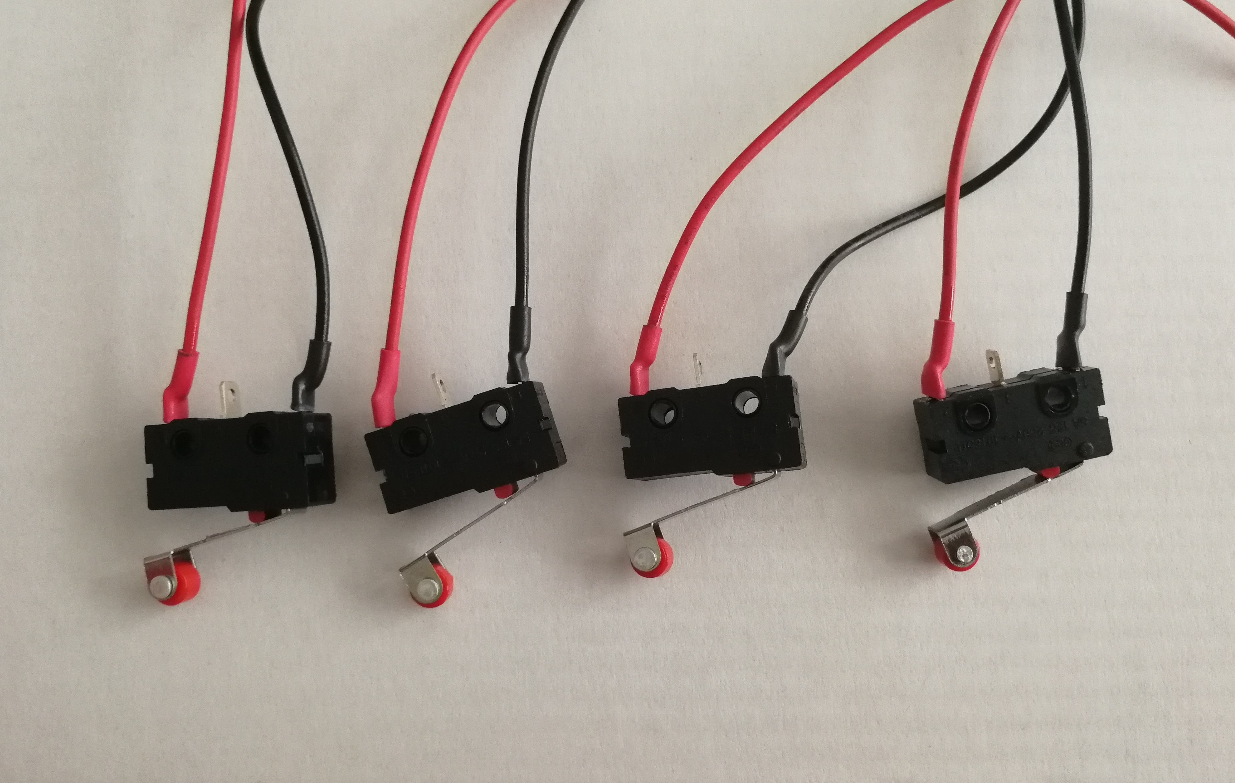
I also printed new end stop trigger that can be positioned on the conduit:
But what I wonder: if I move Z +10mm is it intended to move downwards or upwards?
Maybe Z was the only connector that was right…
I printed a similar endstop yesterday but I have not yet had the time to tinker with the machine.
Positive Z is up, when your tool (bit) moves down it is - (negative numbers)
I zero manually
Move Z with LCD to touch top of piece
I zero all axes with the custom command menu
Then I start “print” from SDCard (no computer connected)
Oh man then I reversed my Z axis for nothing as it was the only axis being correct from the beginning… But as my title says: slow progress!
I wanted to use EstlCam for milling and stuff but the latest version does not support the ATMega chips or at least my MKS Gen v1.4 as far as I know. So lets see what I’ll do with my machine.