Solving Z axis lifting problems, stepper losses

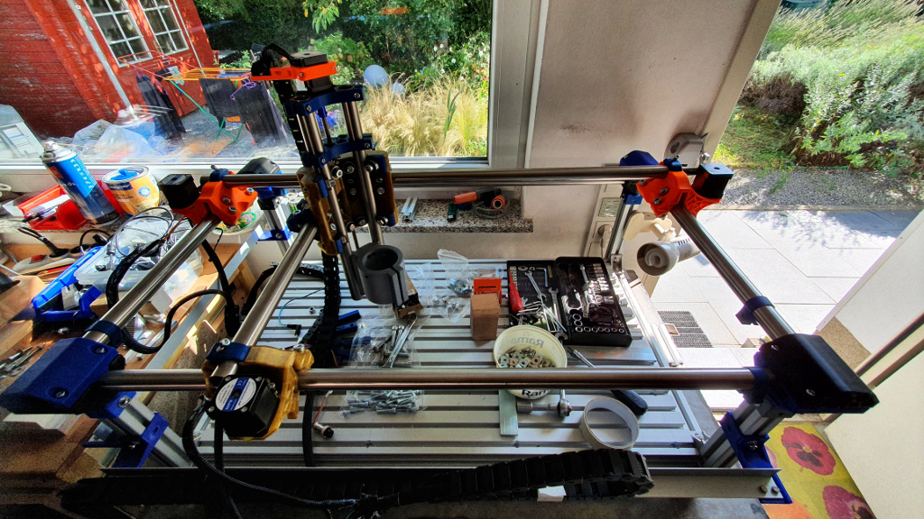
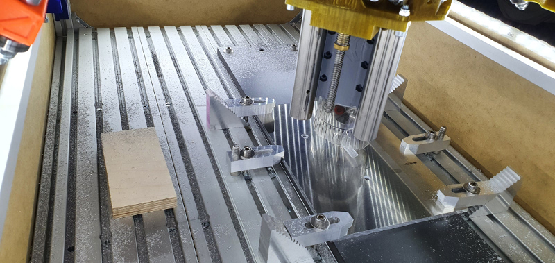
I had a couple of problems working with hard aluminium (AW-7075) using my PRIMO. During miling the spindle/z-axis lifted in steps of ca. 1/10mm and depending of the deepth sometimes up to 0, with normal miling but also trochoidal.

So I have modified a couple of things at my PRIMO.

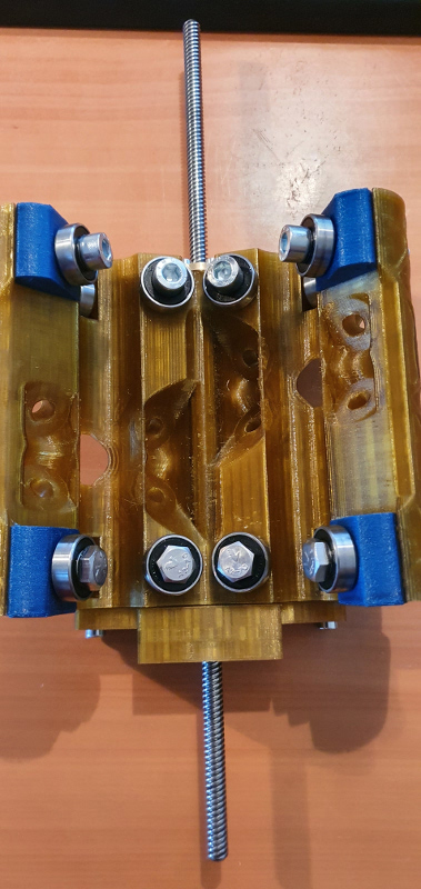
Additional stabilizer / clamping block for thread rod nut

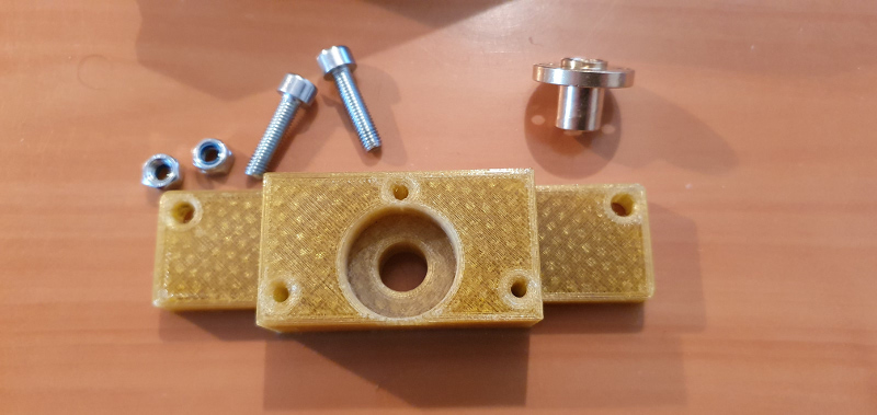
First I realized a new stabilizer or call it clamping block for the thread rod. Mine is a T8x8 2mm, so standard!
This clamping block will be installed at the bottom of the core and keep another nut.

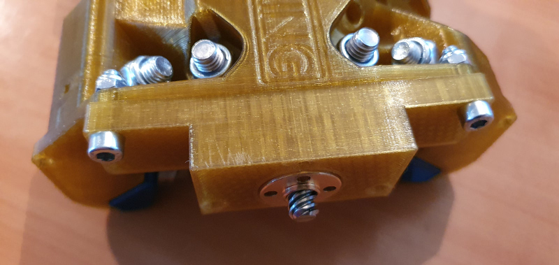
I have designed the block in a way to use the standard holes at the core bottom for screws but also added some holes for other screws (3x30mm) to fix the block at the core. The position of the holes are chosen in a way that there is enough material at core side.

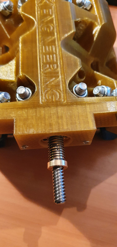
With that 2nd nut you are able to fix the thread rod in a very flexible way that it will not “dance” or “swing” while working with hard materials or if your feedrate in x- or y-direction or even worst in z-direction is too high.

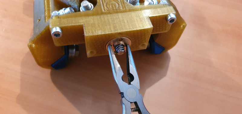
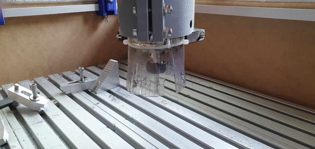
Especially in z-direction e.g. diving into aluminium, I had problems using feedrates of more than 100mm/min. With this addition, I dive into the material with 300-400mm/min (Helical drill with a 3mm drill) without any problems and you can hear that the spindle is not going to vibrate anymore!
I also changed from the normal nut to a anti backlash nut which is even better to handle vibrations.

Really, it is a completly different/new/enhanced way to work, I couldn’t imagine that such an easy addition would have such impacts.

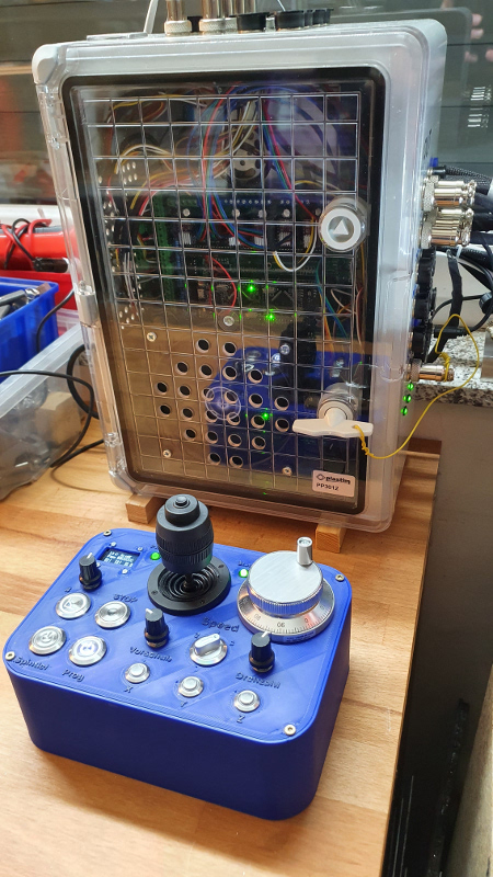
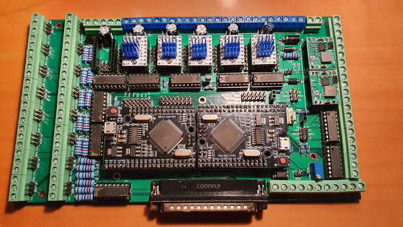
New drivers for my board (TMC2209 V3)
I am using a board based on Arduino Mega with drivers for each stepper. I started with DRV8825 and changed the drivers to TMC2209 V3 (256 Microsteps, 2A).

The TMC2209 have Vref of 1.0V to 1.1V but they work extremly silent and they do not get hot! Even the steppers keep really cold after working for hours!

Difference to the DRV8825:

  • the steppers will run invers, so turn your cable at the driver or change config “revert direction” (typically) Estlcam
  • the driver starts at 1/8 so min. config is 1.600 steps per revolution

Only disadvantages: Price is even higher than DRV8825 and the driver is really sensitive. Disconnecting the stepper on a running board will directly kill the driver! No chance!
That’s it!
Alltogether … I can really recommend using it.

And it results in NO lifts and NO losses.

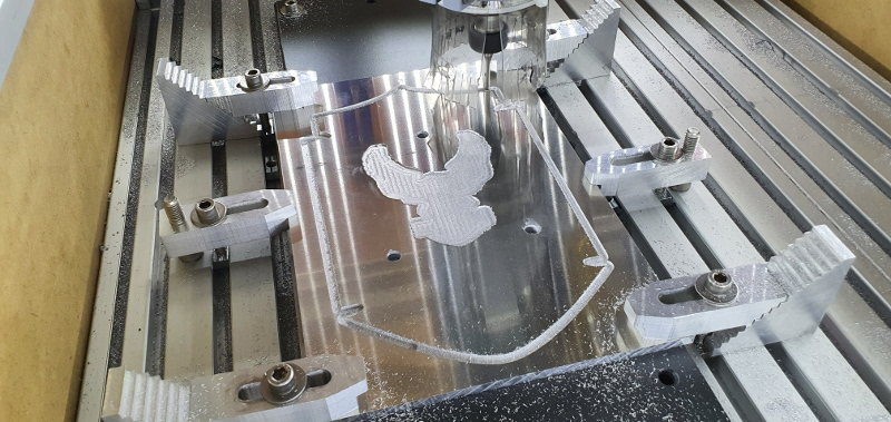
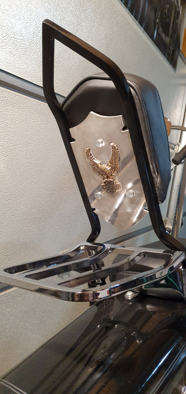
And here the “Final” at a “cool bike” :sunglasses:

Ciao
DJ

4 Likes

Nice work. That looks like a great project.

The design assumes the router weight will handle backlash in the Z. I guess if you’re plunging enough, the router can overcome its own weight. I would not expect that the be the first issue though. Glad it is working for you.

I do not know if I understand what you mean … so I try to explain what was the reason to create the clamping block.
Regarding the standard design of the PRIMO in my opinion one of the weak property of the PRIMO is:

  • thread rod has only 1 point where it is “guided” and this is the point where the nut is fixed on the top of the core.

If you are going to work with weak material like wood, mostly it is no problem.
Working with more hard material like aluminium, independent from the router or the weight of the router, at a certain point, the router starts to “vibrate”. This can only be handled if the attachment (router to core, but also the core itself) is strong and fixed enough to absorbe these vibration.

If this is not the case, the parts from the core - and here also the thread rod is part of the core - will get and take the impulse/momentum (see conservation of momentum).
That means - and I have seen this effect a number of times at my PRIMO - the thread rod at the bottom of the core starts to take over the vibration of the router and starts spinning like a pegtop.
Result is, that the core/router starts jumping when the thread rod is spinning too much.

The clamping block with the second nut or anti backlash nut now prevents that the thread rod is spinning. On the other hand it prevents to be pushed up in z-direction.

Of course, you are right, it is not the only issue in preventing z lifting problems but especially to keep the PRIMO “calm” and having more oportunities in working with harder/stronger material.
Also the drivers TMC2209 did their part in eliminating the stepp losses.

This is the force of the bit overcoming the weight of the router. This is what I was talking about. If you are pushing it hard, it can lift the router. It was designed so the force from the bit doesn’t overcome the weight of the router/core.

If all that happens very fast, it is easy to say it is being excited or not calm, and maybe there is a standing wave that is causing multiple miniature impacts to combine to create a larger movement. But the root cause is that the bit is pushing hard enough to lift the router. Which is why this isn’t a common problem.

Adding anti backlash nuts and extra nuts can overconstrain the system. Overconstrained systems will bind. It seems like you have this tuned well enough that it doesn’t have much additional friction, but be careful recommending that to anyone else.

That’s my $0.02. You don’t have to agree with me.

I think using feedrates - as mentioned above - of 100mm/min doesn’t mean pushing it hard. It is more or less the minimum because otherwise it wouldn’t move.

I agree with you that is seems the core has some problems with standing wave or multiple miniature impacts and this is what I - in my case - solved with the second nut.

I do not agree with the argument, that this isn’t a common problem. In my opinion it is, but as you mentioned - we mustn’t agree. :wink:

And to be honest I do not believe that an extra nut will overconstrain the system, in my opinion exactly the contrary is the fact. It will protect the system to not be overconstrained too quickly!
If you look to other more professional cnc the thread rods are always guided with more than only 1 nut.

I will do that, but to be honest my recommendation was regarding the drivers TMC2209.

Hi DJ, back to the Z-axis stabilizer - can you post of picture of the core with the stabilizer installed, please. It strikes me that the stabilizer hangs below the core – reducing usuable space beneath? Did you have to use a longer threaded rod?

Hi Darrell,

I will add some images here of my z-axis construction. My thread rod is 35cm but of course it is dependent of you z-axis pipes and you Primo construction (e.g. the height of your legs).

So you see that my construction was realized in a way that the mount with the spindle is always “under” the core. The core has always “enough” distance to the material that you work on.

That also means, as mentioned above, the thread rod needs to be/can be longer and the space beneath is not reduce (in my construction).


As you can see in the next image, the thread rod is “always” shorter than the mount with the spindle, so nothing is reduced. The bottom point will be defined by the end of the router.

In my case there is also an additional possibility to mount another stabilizer at the end of the z-pipes - you can see on the foto (black). This is based on the fact, that my spindle holder/mount is not placed at the bottom end of the z-pipes. With that stabilizer it is also possible to reduce the horizontal weakness of the z-axis reducing the shearing force. Another helpfull improvement :sunglasses:

Here in the next image - viewing from the front - you can see that neither the thread rod nor the additional stabilizer is reducing the working area/height of the Primo.