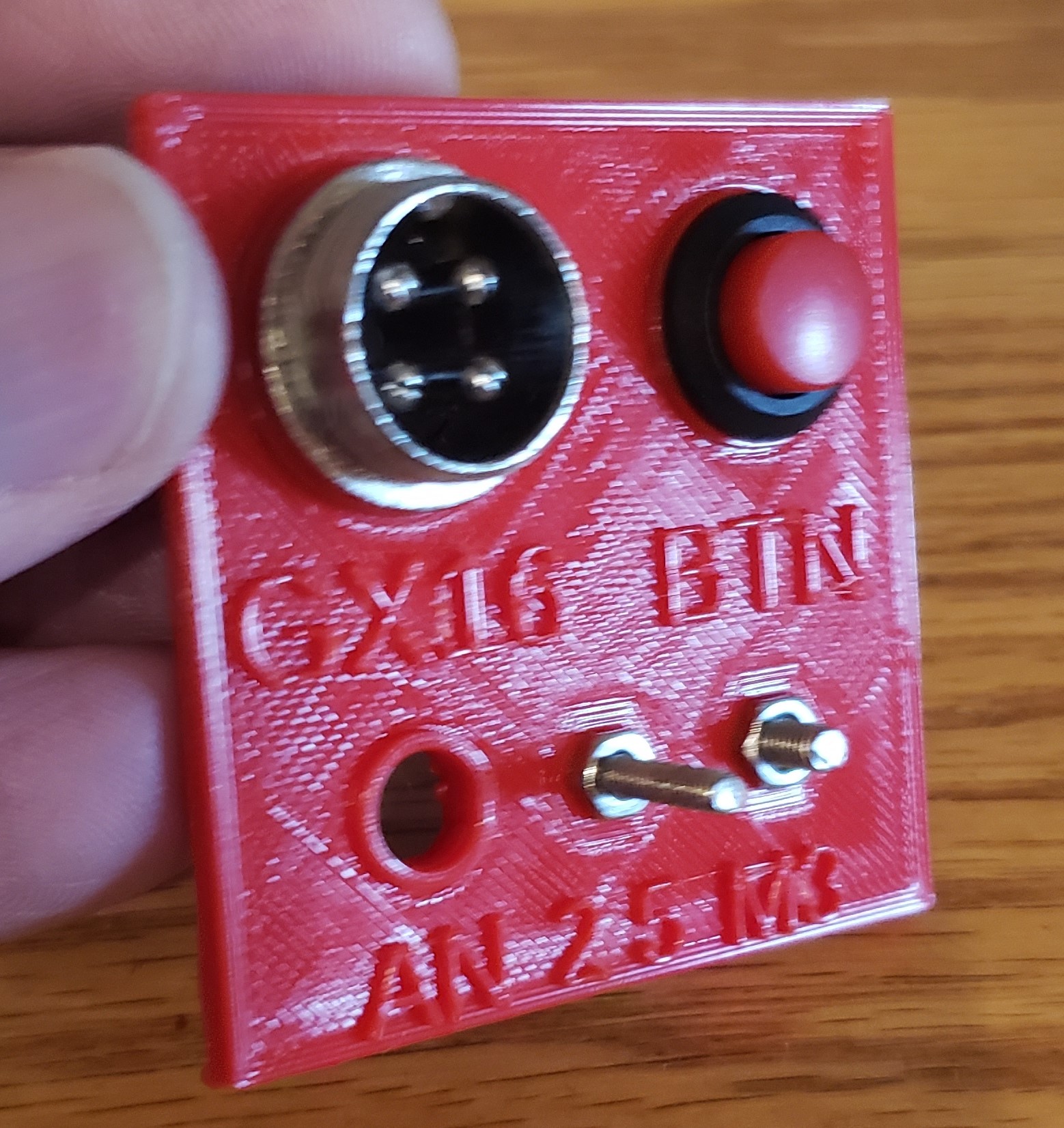
But damn, doesn’t parametric CAD and test parts make the design cycle so much easier? I was having trouble with the size of my nut traps, and after the third reprint of a 2 hour part, I saw a video on parametric design, and it clicked. I spent an afternoon reworking my CAD to be parametric, and added a small test part that contained all the parameterized features. Now it’s about 20 minutes to print off a test (still having problems with my antennas mount), and I know that any change I make to those features is auto-propagated to the entire model.
4 Likes
For anyone who doesn’t know, or is confused about it, you can check out this project on OnShape (project link) Note that the actual values for the parameterized variables are part of the link!
Picture-heavy Description
Setting it up is actually pretty simple. start with the configuration tab: 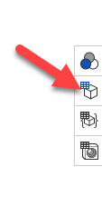
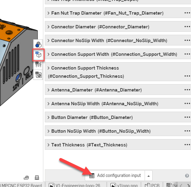
Then add a value:
I’m using variables, but you use discrete values from a list, or a checkbox: 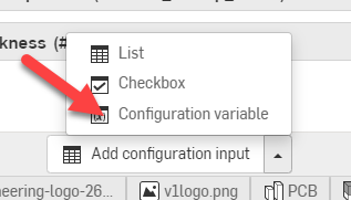
Then it’s just plugging in your default, min and max values: 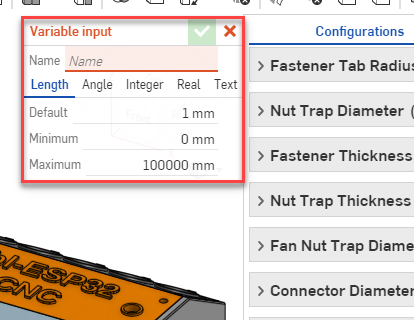
The min and max values make the system angry if you try to take the value outside of those limits. As an example, I used 16 mm as a minimum for my GX16 value, and a max of 17 mm. If I need more than 17mm, I have to go all the way out to the part studio, and edit the configuration variable to have a different max, then I can change the actual value. You could also set up variables for angles, or text, or just bare numbers (handy for linear or rotational patterns).
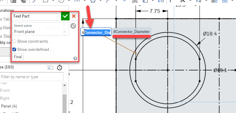
Finally, you use those variables in your sketches, where you just use them where you would normally use a fixed value, but you use the #var_name instead:
You can even use them in expressions:
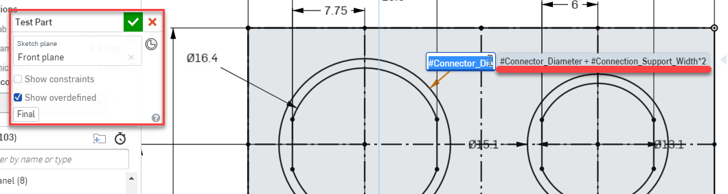
When I have multiples of a feature on one sketch, I use the equals constraint to make life a little easier on myself. And then, you can change all the features from the part studio: 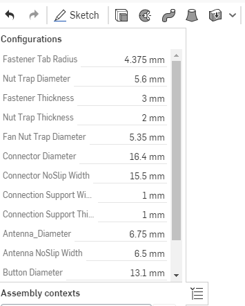
1 Like
My tip here is be very careful. Doing it for one type of feature is not too bad as long as you know how big of a range that variable will be.
How this gets ugly is say you design for ~3mm holes, in a square plate. Then someone decides they need 10mm. So not only do you need to think about hole size everything need to be dependent on those sizes, hole spacing, and plate size. You end up with a lot of equations that you need to carefully decide how they behave. And what if you need 2 holes instead of 8?
That is why when people say “aren’t you designing the MPCNC to be parametric?”, yes but I have a size range in my head (23.5-25.4) so every single dimension is not fully parametric to any size ever.
3 Likes
Yeah, I would definitely only use it for relatively discrete features, and specifically for features that interface with external (to the CAD design) parts. Like I’m using it for M3 and M2.5 nut traps, the connector openings and relief heights. And it could be easy to slide down the slippery slope of parameterizing everything, and then it’s just silly.
2 Likes
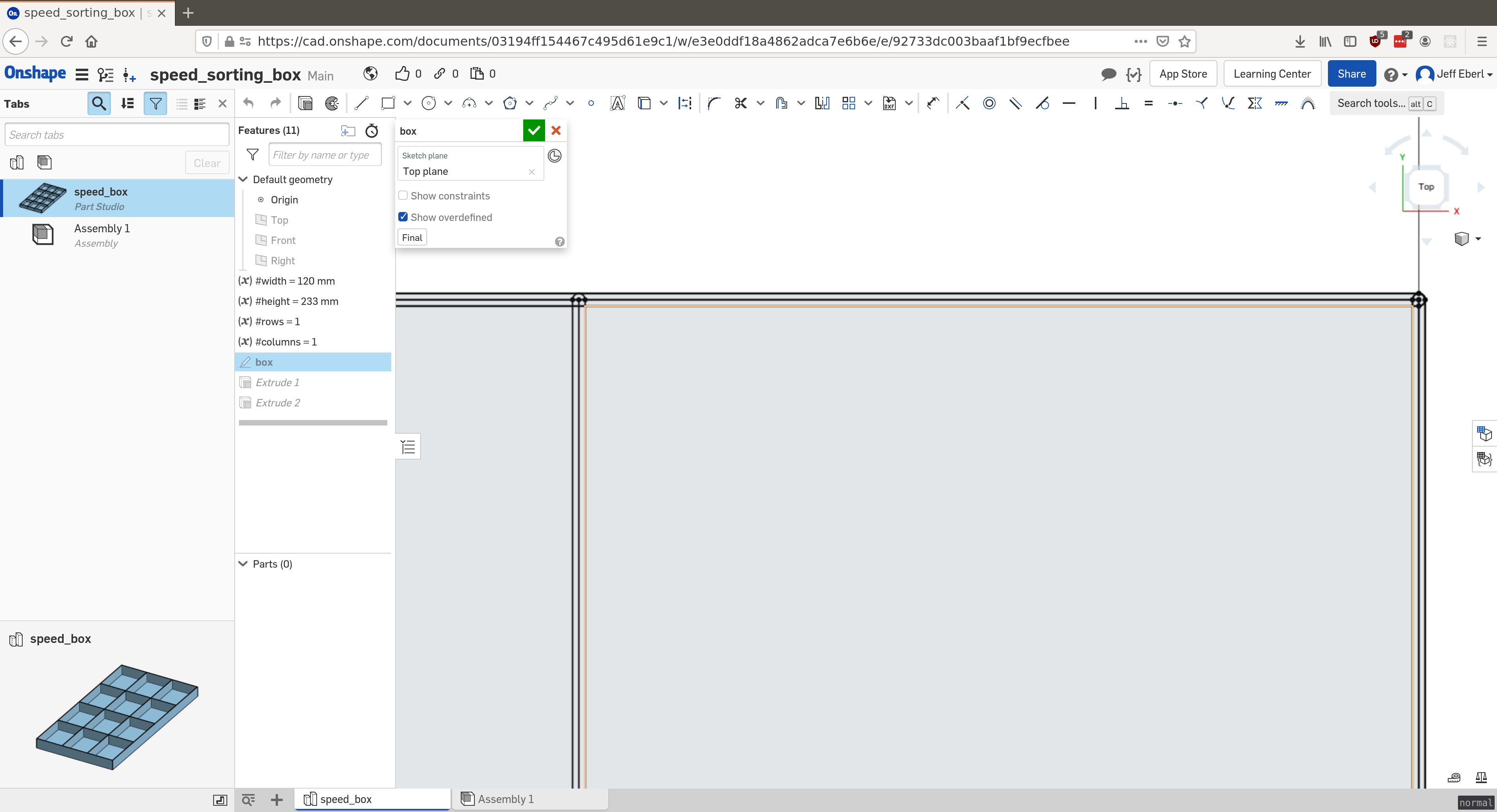
I wanted to make a sectioned box, with parameters for length, width, height… OK no problem. Then I wanted to make it segmented inside, so parameters for number of rows and number of columns. OK no problem. So I make a sketch, use the variables for length, width. I draw some lines, and use the repeat tool with quantities of rows, cols. Then I add some restraints so the bins take up the whole area, and I’m almost done with my sketch. Now I need to offset each line to make a wall thickness, and then I need to extrude the floor the floor thickness and extrude the walls the height parameter. But this involves a bunch of clicking, and when I change the num rows/cols, everything gets dorked up.
So that’s where I’m close to loving parameters, but far from really enjoying them. Maybe I need to flip it around and make the walls one at a time, with all their extrusions and offsets, and then repeat the 3D shape and boolean them together?
For something like that I think I would almost do it in CAD the order you would assemble it. Sides, then bottom, then interior features. A lot of it is making things coincident and tangent, not so much equation driven.
2 Likes
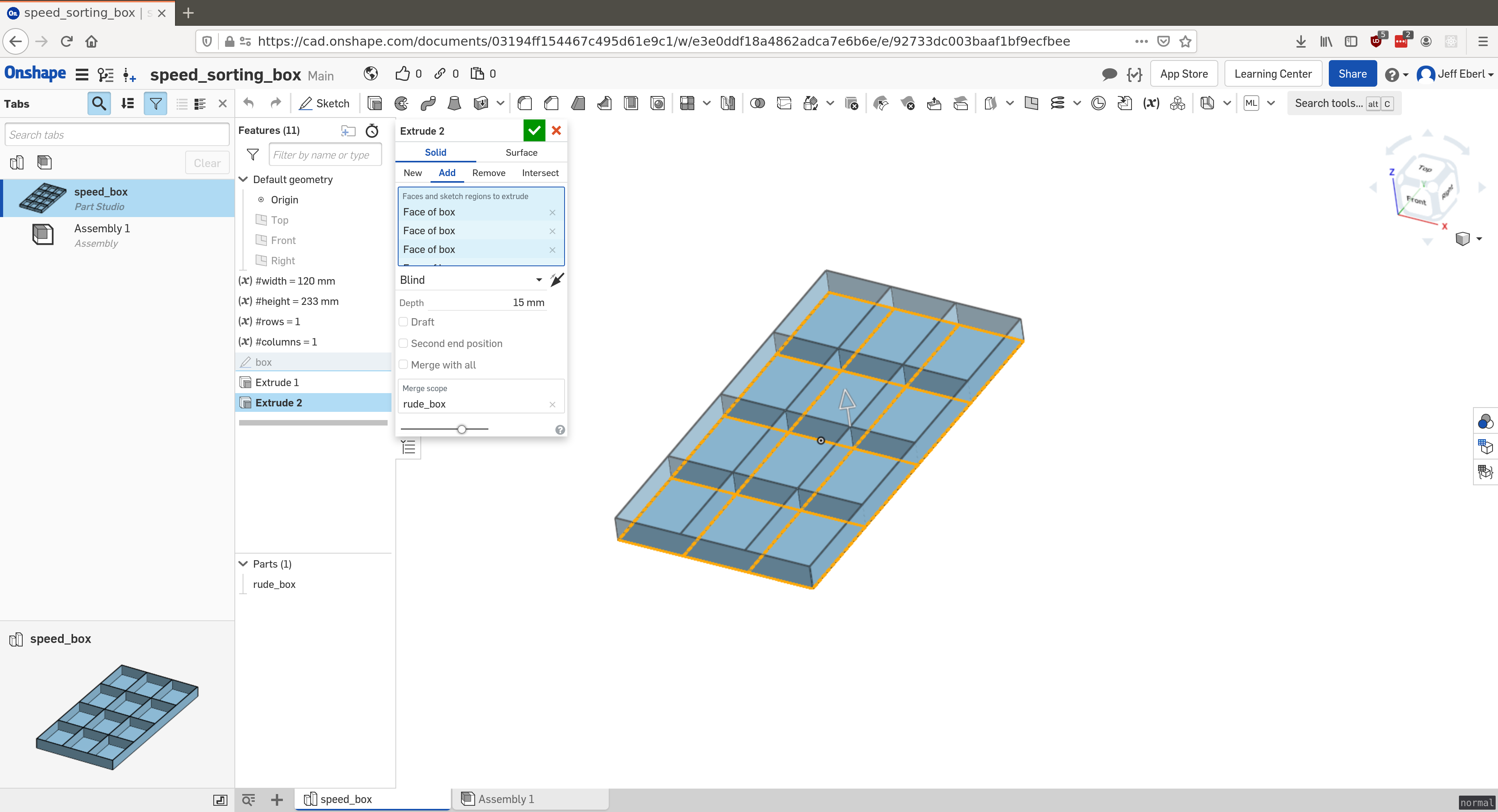
I can easily draw and make one, but I wanted to be able to make it legitimately parameterized. I want to use it as a test print part for my printers, and have the bottom be 1 layer thick and the walls one layer thick. That way, my printers can make lego sorters while I test speeds and adhesion stuff. But I want to be able to make ones 2x3 or 3x4 easily enough. The trouble is extruding the interior features require pointing and clicking, so the inputs to the extrude steps aren’t controlled parametrically.
1 Like
Silly goose, that’s not parameterized, that’s spoon-fed by an autonomous function. You’ll need to learn how the Feature Studio works to get that sort of laziness done. 
Sounds like you are doing it in 2 steps, extrude block, then extrude/cut interior. If you do it in one step, extrude the wall thickness then you are done.
It was something I learned late in life when I was figuring out how to design for my laser cutter. Talk about powerful knowledge. It’s amazing.
I’m still learning best practices on how to start with a design using construction parameters so I don’t break a design with changes later it. It’s tough.
Yesterday I did my first feature pattern along a path in Onshape. I’m still tweaking my dust shoe design and I was making holes for brush bristles to stick into. It’s so cool to be able to even space 40 holes around an irregular perimeter, and then change it to 45 to fill it in better. Now I need to 3D print a miniature funnel so I can get the bristles into the hole. That is a tough challenge.
I like Onshape so much and it is doing almost everything of what I need, especially with the Kiri:Moto plugin. But Fusion’s CAM stuff, and now a nice tabbed box maker extension, is tempting me. Just hate to go to a stand alone app.
Maybe the issue is that I don’t have the right parts as “construction” lines. I am extruding it in one extrusion step, but I can either have it extrude the whole sketch, or just a face of a sketch. The parts are separate, so I have to click a bunch of places.
I see what you are saying, that is an onshape thing. I bet there is a setting but in solidworks it knows what is the shape by defualt, I ran into that the other day with the extruder mount.
At the same time you do have multiple sections closed, non continous. That would not work in solidworks either.
I think I can do it my just extruding one side and then multiplying it across the shape and joining them back together. So the multiplication happens in 3D.
If that makes sense.
A square is one continuous area, if you put a real line through the center you would have two sections and would need to specify which to extrude. But if that was a construction line typically in solidworks you do not need to specify, but in onshape I needed to still specify.
So if you went back into your drawing and trimmed the real lines and did not trim the construction lines it might work.
I agree with that, but then I wouldn’t be able to parametrically trim the lines.
I’m just waiting for Jamie to pop in with something about how I should use openscad.
1 Like
I would need to see the part I think. Not really sure why all those extra lines are there to begin with.
Looks like he drew them as a line drawing, then offset to each side 1/2 the width of the wall. But used full lines for everything. I take that back, he didn’t offset to either side, he slotted the line.
1 Like
Yeah. That. I can’t remember, honestly. I think I slotted them. I first copied the side a set number of times and then I made them fatter with the slot tool.
I don’t have a good grasp of when to use construction lines, so I usually just don’t.
I could probably make a construction line, and then a line, and then determine their lengths with parameters, and then multiply them to make them go across with a pattern and then I wouldn’t have to trim anything.
But the point of me bringing this up was really to point out that sometimes the parametric stuff isn’t super simple. Even on a simple shape like this, the overall width/height/wall thickness is easy (within some bounds) but then it gets a little tricky quick.
2 Likes