I’m trying to make a MFT table (MDF top with 20mm holes in it). And because the holes needs to be very accurate, I started to calibrate my Lowrider 2.
I use end stops on all axis. So, I started on the Z-axis by measuring the differences in height along the beginning and end of the x-axis. made adjustments with the M666 command until it was perfect. M666 Z4.3 was the end result.
Then I started with the Y-axis. Made a little dot, with a 35-degree bit, moved 850mm and made another dot. I adjusted with the M92 command until it was perfect. M92 Y100.12 was the end result.
Last axis was the X-axis where I did the same thing, made a little dot, moved 550mm and made another dot. M92 X100.18 was spot on.
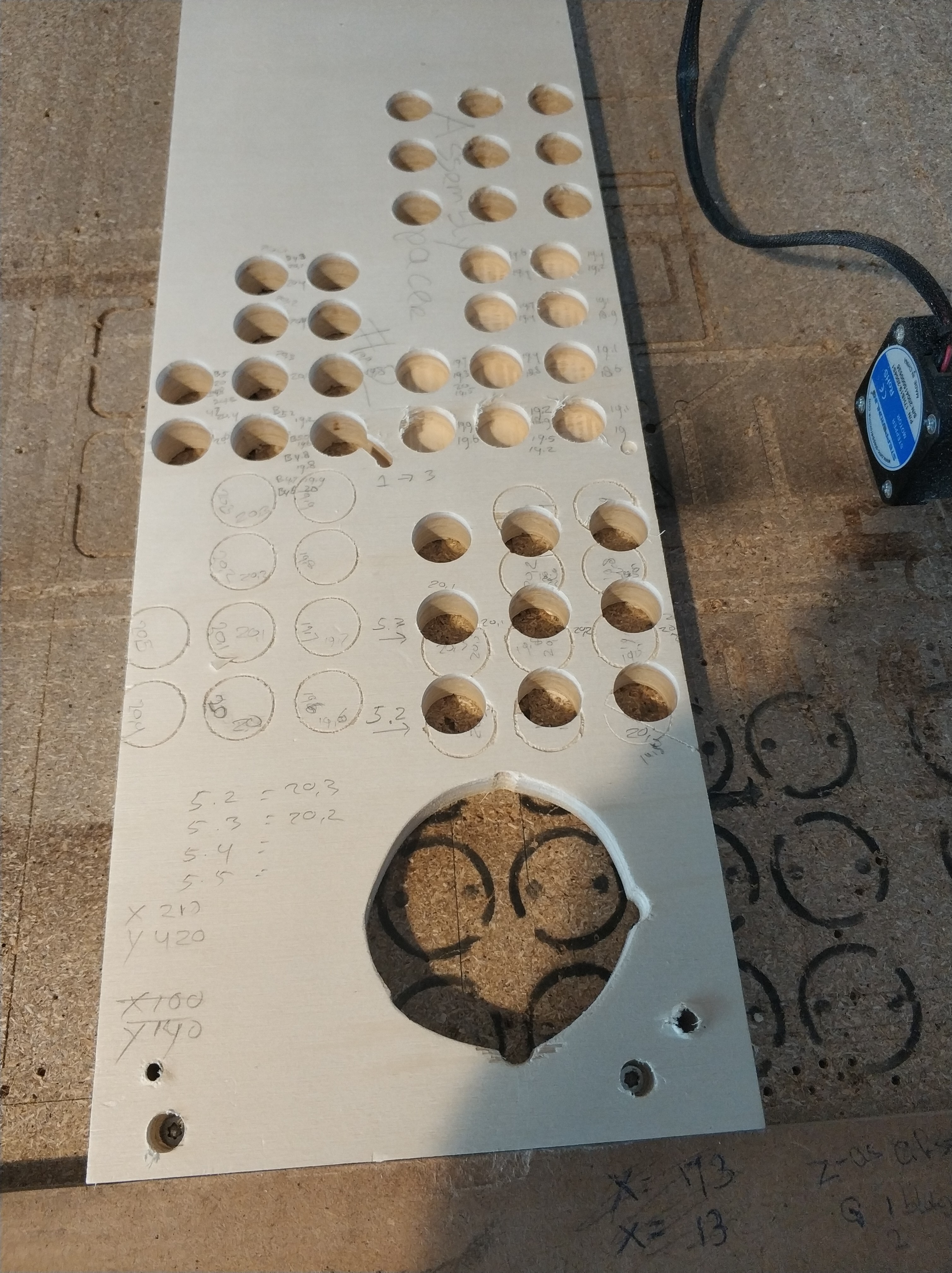
Then I started to make some test holes. I drew some 20mm holes in Vectric Aspire and made a pocket toolpath with a finishing toolpath at the end. It took some experimenting with the diameter setting of the bit in aspire to get the right size holes but eventually that worked. The perfect size hole, to fit the bench dogs is 20.2mm.
The only problem I have is that some holes are perfect round and the perfect size, but other holes are oval. Where all holes at the y-axis are perfect 20.2mm the z-axis on some holes are perfect 20.2 but on other holes there 19.8mm.
If they were all undersized, I could understand. But because some are good and some are undersized at the X-axis, I have no clue how to troubleshoot this.
Somebody is going to say “grub screws” so make triple sure they are all tight.
I modified something on my 611 plate, but I can’t remember what anymore, and it caused some binding on the belt, similar result.
Also has some trash get in the way of the wheels, cause a small amount of deflection. I’d be surprised if that was it, but i suppose it COULD cause a little more resistance on one side than the other, and it’s easy to check.
If you’re not already, make sure you are using finishing passes. And pay attention to the climb vs conventional milling.
Finishing passes are really important for anything that needs dimensional accuracy. The rough pass leaves 0.1mm or so of material and the finishing pass comes through at dimension and hopefully is removing so little that it has nearly zero force on the bit and can track very accurately.
For holes that are too big, one possibility is that the bit is pulling into the work and that is causing it to pull in and grab too much. That could be caused by climb milling.
By “cal” I assume you don’t mean adjusting the steps per mm. If so, then you may have made the holes that were 19.6mm and made them 19.8 while making the already perfect 20mm holes 20.2mm.
And with calibrating I indeed mean I adjusted the steps per mm. I used my full length and width of my table to check the distance and adjusting it with the M92 command. Now it is spot on. Just to be sure, I checked it again today and it is still spot on.
To get the bit pulling into the work out of aquation, I tested today with a 35-degree v-bit going in only for 1 mm.
Also tested the differences between climb and conventional milling, results:
climb milling
Y-axis 0.3mm short
X-axis 0.1mm short
conventional milling
Y-axis 0.4mm short
X-axis 0.6mm short
I can’t figure out why if I the measurements over the full table are perfect but circles becoming ovals.
any suggestions?
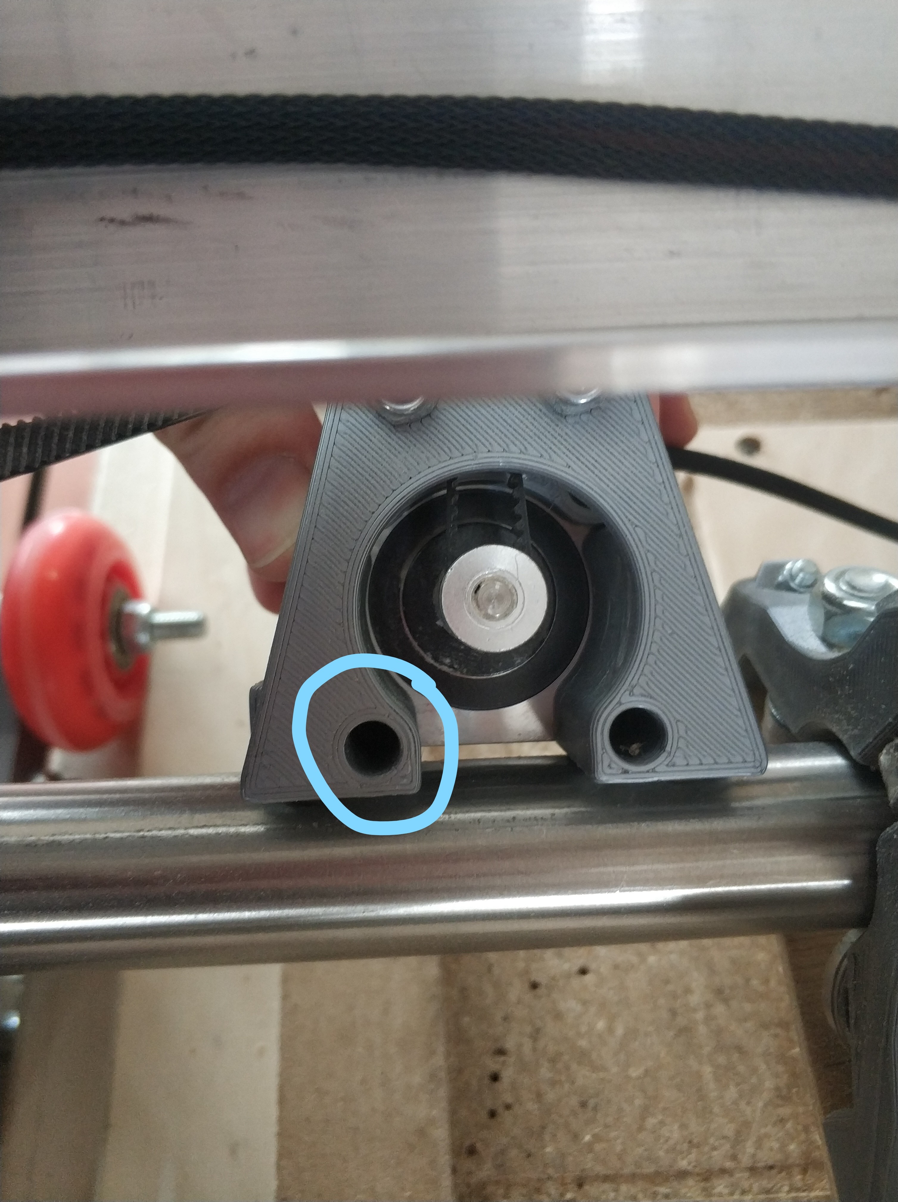
edit: I noticed some play at the router plate. I guess there is a screw missing that holds the Z-motor to the plate.
I’m going to check that first and will be back to share the results.
This screw was missing… After putting it back, and this time with thread locker, the circles became perfect circles.
The circles are still a little but undersized. I will check my calibrating again, maybe the missing screw had impact on that too. If that doesn’t fixed the undersized holes I will just make the holes al little bit bigger in Vectric.
I did some more testing today and the adjustments I did with the M92 command are still spot on.
Tested on a length off 115 cm for the Y axis and 55 cm for the x-axis .
end result are:
M92 Y100.13
M92 X100.18
also thanks for the climb hint. I did some testing, with a 35 degree v-bit 1 mm depth, and climb milling gives me better results then conventional milling.
both give perfect circles but with climb my circles are 0.1mm to small and with conventional is 0.5mm to small. I will learn more about the differences between both because I have no clue when to use on over the other.
I pulled the belts tighter and that indeed helped. I changes the M92 X and Y back to 100.0. I had to pull the belts tighter then I thought I needed, but it measures perfect now.