so I followed the instructions on building the MPCNC Primo and am currently stuck on squaring after installing the core and z-axis.
Before adding the core no squaring was necessary, all measurements matched. But after installing the core, my y-axes are off. After randomly moving the core around, my left y-axis always has a +2mm difference between truck and front corner compared to the right y-axis. As the manual mentioned, I tried to adjust the core tension bolts but it didn’t change anything. So I am not sure I am understanding the concept of tightening and alignment.
Ay ideas on how to solve this or can give me a better understanding on the bolt tightening concept?
You could also zip tie a pen to the Z axis and draw a square on a piece of paper and measure the diagonals. It’s possible the one truck just rides a bit off from the other, but the gantry itself is square… at least, that’s how mine is. I think my diagonals are ~1/16" off across the entire size of the spoil board.
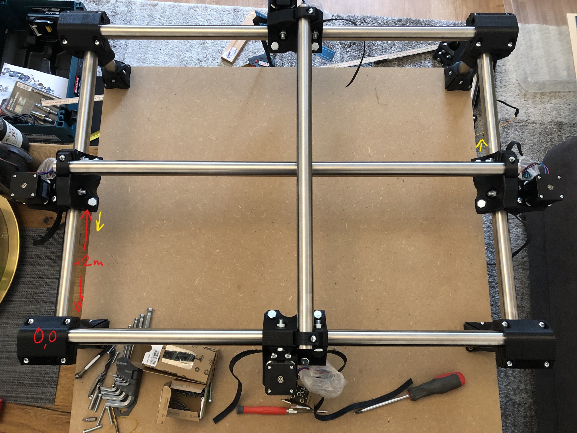
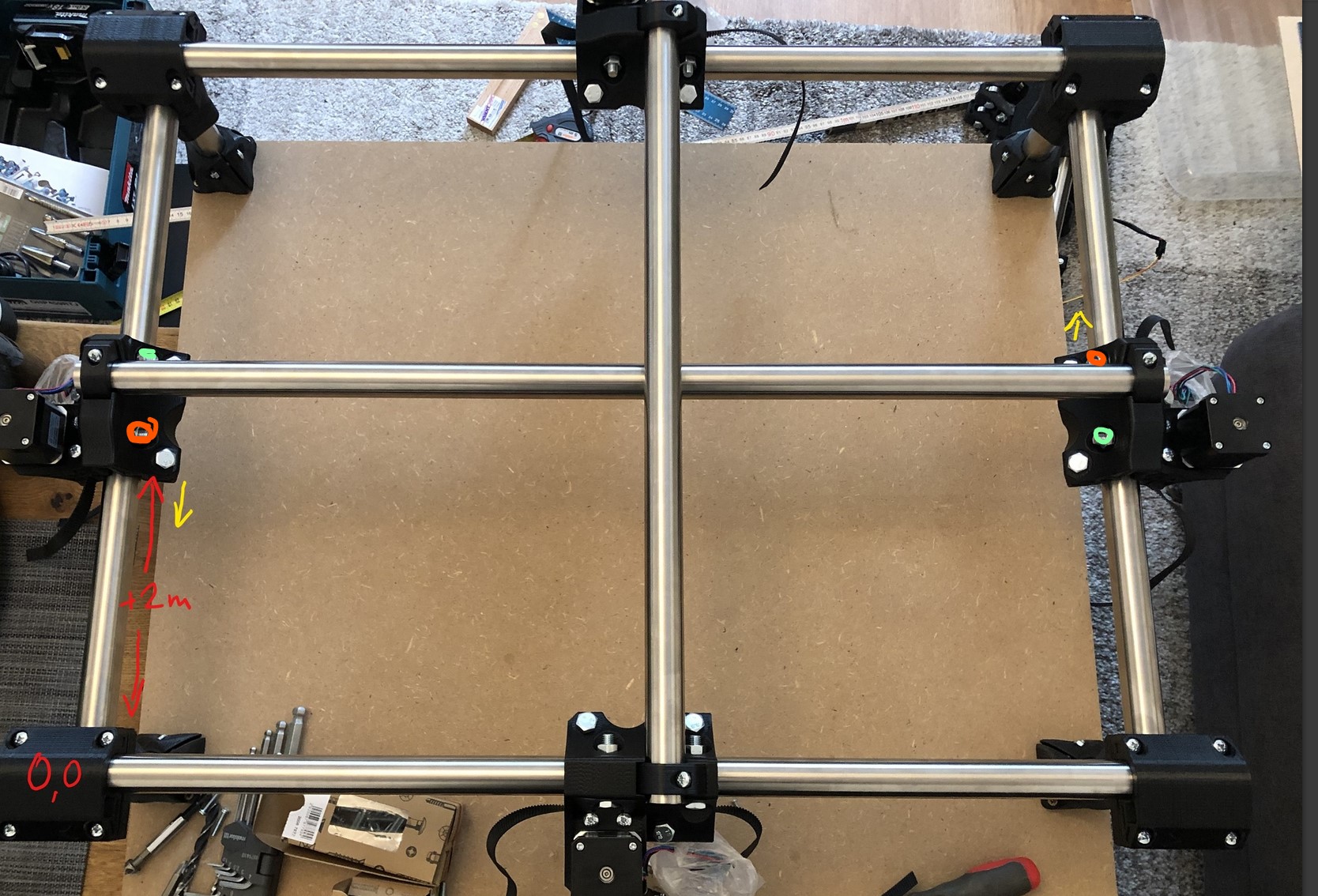
The left truck is consistently +2mm off, meaning on the Zero-Point aswell as after moving around in a random pattern and stopping somewhere in the middle.
I also did the testprint. I measured between 149.7 and 149.8mm so I should be fine right?
@niget2002: That’s what I was thinking about aswell. Since it is consistently off, maybe the result is still square. I moved the core from the very left to the very right and measured the distance between front truck and core, no difference. If my logic is correct this means the core hasn’t moved in the front/back direction which indicates that the gantry is square. Unfortunately I am still waiting for my pulleys, so before that no live testing.
So is that measurement you are showing too large or too small?
The gantry clamp tension bolt we can see in that picture, the only one. Tightening that should move that truck closer to the corner, loosening moves it away. The other clamp on that same rail…will make the other truck closer to it’s corner, and loose=further.
If adjustments do nothing it means all your adjustment points are too tight.
Have a look at the instructions again and see if my diagrams make more sense now.
Ok that is what I was guessing. In this case the truck measured is further away than the other one. So I should tighten the visible bolt and loosen the other one.
I tried that but no result. Not sure if my tightening is too shy or the settings are too tight. If so, which bolts should I reset? Only the two bolts, all four core tension bolts, more?
Just get all bearings touching then adjust by changes which ever needs to be moved closer to that corner. (from the perspective of your measurements). Tightening bolts moves the truck closer to it’s axis minimum corner.
Did that, zero changes…not even a slight trend towards a smaller difference. I tightened the bolt to the point that the core clamp slightly cracked. Might need to reprint that one. I even tried loosening all four bolts even though it should not make a difference…which it didn’t.
I measured the distance from front to back corner on both sides. They are the same. I am out of ideas…
3d print a 150mm x 150mm open square that’s about 8mm tall.
Measure the diagonals and let’s make sure your printer prints square. If it isn’t then it could be possible that the core is slightly skewed? (Really just spitballing ideas here)
Also done, the results were good I think. But yeah, not sure what else it could be. The pulleys arrive tomorrow, so I might just try to finish it and check the actual live results. If that fails, I guess I have to reprint the core.
Don’t reprint the core. At least not yet. This is a new build, and you are the first with the issue. So with a burly build this would be the thousandth time we heard something and would have a quick answer. First time…we need a bit of time to sort things out. So lets just keep working this one step at a time.
First and foremost you should have at least 4mm adjustment on both rails. If loosening all 4 tension bolts does nothing we have a problem.
Even if you over tightened your core/Z you should still have adjustment available.
Take a step back look for any obvious issues. You are not using my prints or my hardware so just take a good look for us, any other issues? Did you get the rollers sitting square on their own without the core on? Did you tighten them so much you can’t move them with the core attached?
First of all, thank you for stopping me impatiently rushing to conclusions!
I completely removed the core and measured the trucks again: they are off! I don’t know if I screwed up my measurements before or if it moved for some reason.
So I loosened all truck screws, tightened them just enough to sit on the parts: still off. I looked at the manual and played a little bit with the tenion bolts, but no results.
Before I overtighten anything: If I move my y-axis all the way to the front, the right truck is touching the corner but the left truck has 2mm space. How to I adjust that using the truck tension bolts? I didn’t fully understand the instructions in chapter 4. I know I need to move the left truck closer to the front and/or the right one further away. Which bolts would need tightening and which loosening?
Also, any indication on how the overall tension should feel like if I move the axes? Should I go back to the step with the 45 angle rail testing? If so, what exactly is considered slow movement?
An overhead shot, will clear up what you are trying to do. Just like the instructions, show the whole machine and what you are trying to correct. Have a second look at the instructions, the tension bolt closest to what you are trying to move should move it.
I am getting concerned that nothing seems to move for you.
Did you print with my infill recommendations, with PLA?
You should be able to tighten the tension bolt nearest the yellow arrow on both sides, as well as loosen the other tension bolt on each one. Tighten the orange, green can go looser if possible.
That absolutely has to move it, loosen and tighten the gantry rail clamp on the truck. If it does not move you must have a bent rail?
Thanks man…you did it! I think all the “don’t overtighten” warnings made me a little bit too scared. But I went out of the cofort zone and was able to adjust the 2mm. Core back on, a little more fine tuning and now it’s perfectly square.
Great clarification on the suqaring process, I think this will help a lot of first-time builders in the future. Now I can finally get to the electronics!