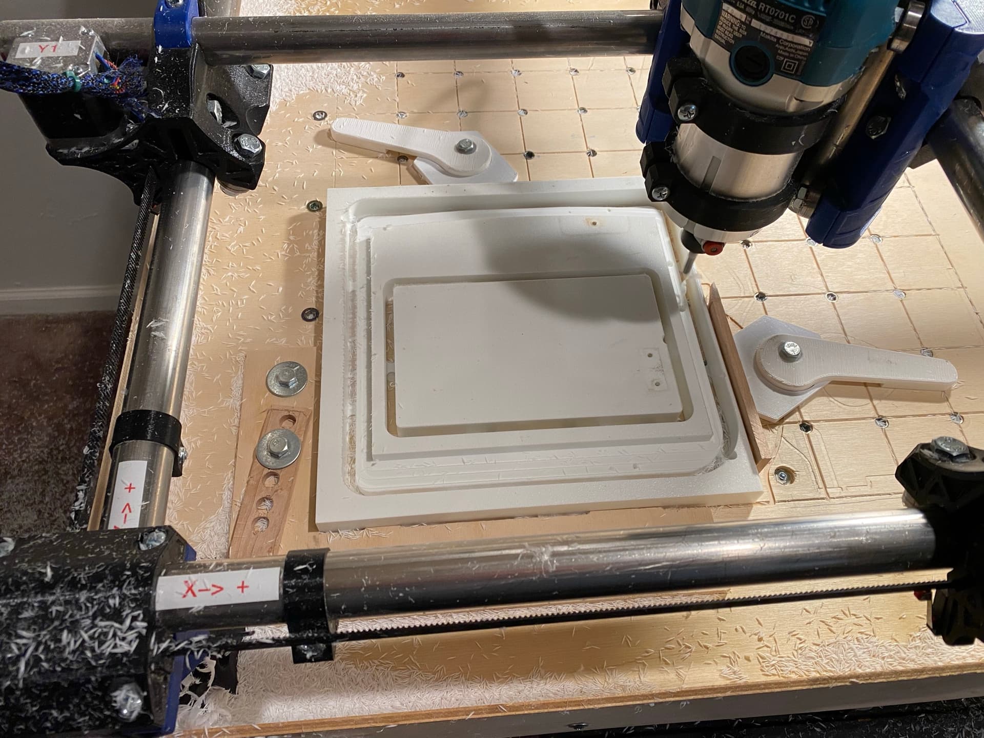
So I’m on my second year with my beloved Primo and I decided to replace my XY zero zero reference guide. It’s where I slide to stock to the 0,0 corner before clamping. The old one was pretty chewed up.
Anyway I wrote a short g-code to cut a fresh X and Y edges and noticed it was out of square by maybe 2-3 degrees. I checked my trucks if they were square but now they are not. I did notice Ryan updated the Truck squaring cheat sheet. Seems clear.
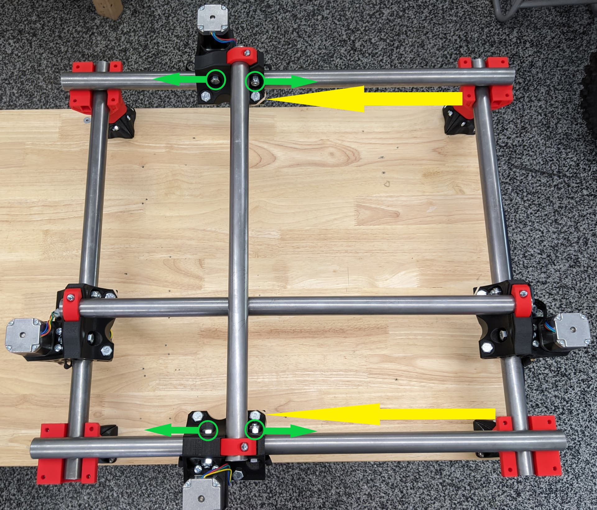
Question: It seems obvious but I think I’ll start by loosing the machine screws, but I assume I should work in opposite diagonal corners to get them square an do baby steps at tightening.
I also assume the steppers should be off so they are free to move?
Finally the photo shows the rail caps being off but I assume it’s okay with them on?
BTW I’m off about 5 mm on each axis but never had issues on my projects.
From your pictures, it appears that you have dual end stops. This will fix a lot of error, in my experience. Within 5mm is probably OK, but of course it’s nice to have it just want to be square naturally.
Once you reach the end of the adjustment range, it will stop moving, and that range is tiny. just a touch of the wrench on the bolts makes a difference within the range where it adjusts. I start out by loosening things until the side bearings can just spin by finger That’s already loose. 1/3 turn from there should snug them up so that it’s difficult to spin any bearings from there with a fingertip. then about a max of another 1/2 turn and things get too tight and stop adjusting.
I will try that. I have a hard time getting my mind around what the geometry is doing when I tighten one side why it would angle? But will try. I used the dual end stops and when it homes I felt when I disengaged the steppers and it “pops” over a little I was out of line but like I said all my projects are pretty accurate.
Because there is some room for movement in the geometry of the truck. This is how it can adjust for tightness.
The space where that top bearing sits leaves a little extra room beyond what the bearing needs. Tightening the bolt there squeezes the part together, turning the other 4 bearings into a bit of a trapezoid shape. The side bearings get a little closer together. That’s why I suggested starting with loosening off of those. Once you get to the point where there’s no more room for movement, you’ve also used up all of the future adjustability of the machine, so if it loosens from there because the plastic flexes over time, you can no longer adjust it back in spec. Ideally that point where I say where you just stop being able to turn the side bearings with your finger is where you want it, because that leaves the most future adjustability.
Last time I made adjustments to my Primo, I left it there, and never really squared the trucks past that. The dual endstops are able to square the machine, and it holds square as long as the motors remain powered up, so I figure that’s good enough for me. It leaves the most future adjustability before the trucks get “worn out” and need to be replaced.
Thanks I got it down nice. I totally agree and feel your advice on tightening just until the bearings touch is spot on.
During the initial build I took that approach at every juncture and it produced a good end result.
Turns out my X was still spot on and the Y I gently got to maybe 1-2 mm. Then the dual end stops final tuned.
I really like your cam system, but I am not familiar with Fusion, while I can work with Autocad, I kindly ask you if you can share your project in DWG or DXF format. Thank you
Sorry I checked and fusion 360 won’t export as DWG or DXF unless you have a paid subscription and I have a limited hobby license.
I can save as a STEP file if that can be imported. Ironically, they are all autodesk products.
Here are both versions. STEP and native fusion 360.
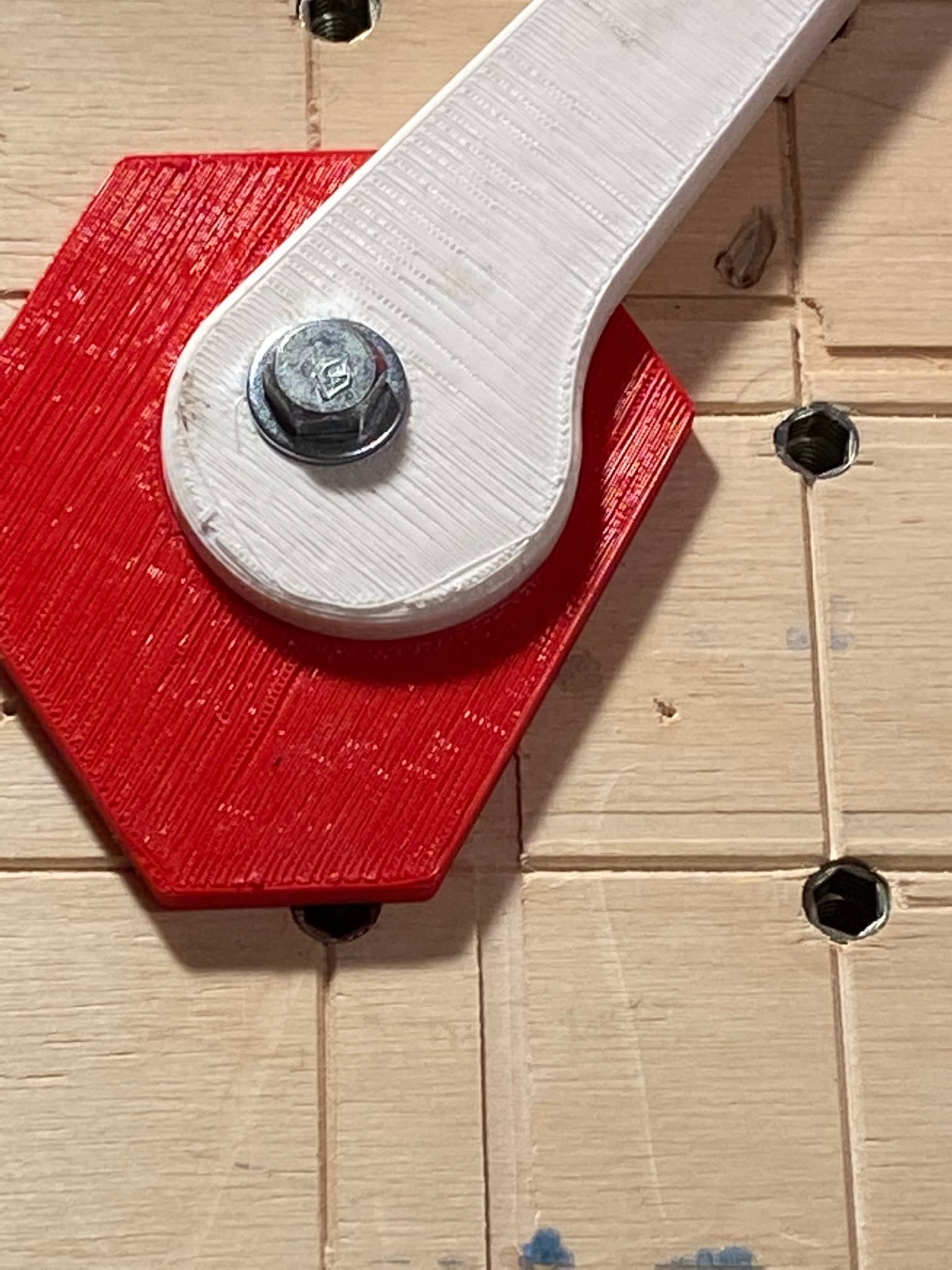
My spoilboard grid is on 50mm centerlines.
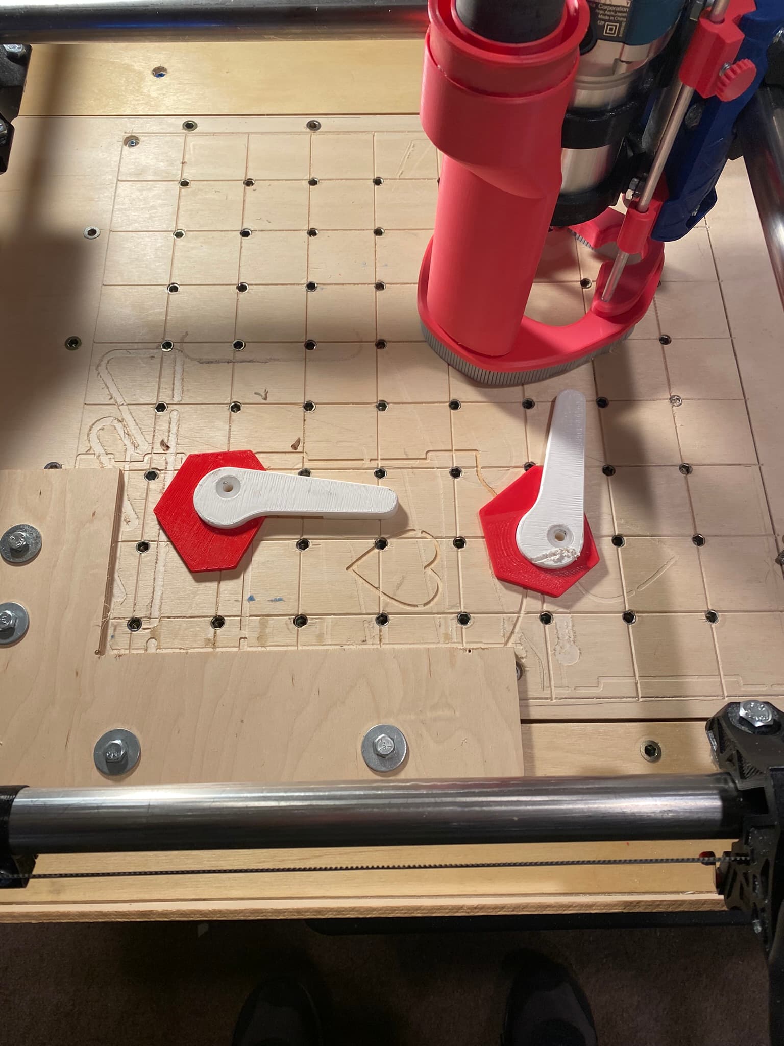
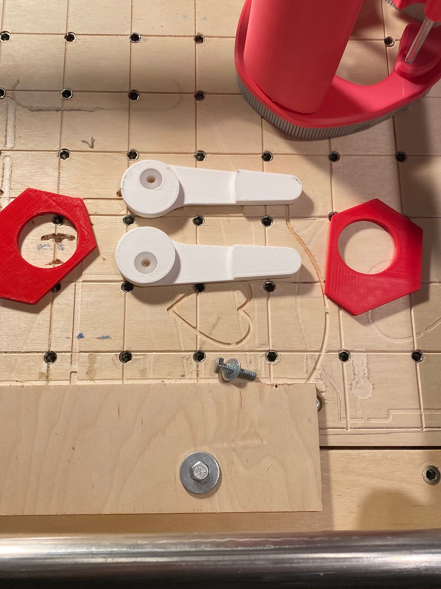
Also, I used a simple nylon bushing for bearing strength and used a steel washer which acts as a nice lock with the 1/4-20 hex nuts as my threaded inserts are 1/4-20 (I am in the states). Cam Lock System v10.zip (201.1 KB)
I don’t think it is worth it. Onshape has a free for hobby license too. And there is FreeCAD, librecad, tinkercad, SketchUp. A lot of choices. I’m before buying, take a look at the YouTube videos on some of them. You will get a feel for what you might like.
Thank you very much, you are very kind. I was able to import the Step file so I can easily adapt your idea to my MPCNC table. When I am finished I will send you the images and files of the result. Thank you
I actually used all of them and at one point was a SketchUp fanatic as I have always done traditional woodworking and SketchUp is very well adapted and accepted in woodworking world. Never thought I’d part from it.
It was when I started getting pulled into the CNC world that I started using Fusion 360. Before I retired from Molex one of the last assignments was to implement a new global software solution as we were falling behind the industry. We settled on Siemens NX even though I like Solidworks a little more. But I really was convinced that parametric modeling was something we could benefit from especially for connectors.
It just is crazy how much cheaper the products have become. We were spending literally in the millions for our seats but there are so many other enterprise level requirements.
Worse part about those assignments you always tick half the people off no matter what we picked.
Not sure if you get exposed much to Signal Integrity but SI software and the computers it requires was a whole other realm dollars. Crazy money. But it does narrow the players.
Pulling those together made me realize there are a couple design improvements that can be made. One is making the parts a little thicker and perhaps having slight overlap if a couple mm flange around the handle to keep the spacer piece down and not ride up.
Also I was thinking maybe a 5 sided space instead of 6 sided?