I’ve been running the LR2 for a week now doing little bits and bobs, nothing with precision or square corners. I started cutting out a box for the controller but then quickly realized how out of square the machine was. I read through how others have squared it and was trying all sorts of things but have hit a road block.
My Technique for checking square:
Installed a fine point scribe onto the router board with a clamp and some hot glue in a tight fitting hole.
Resting the gantry on some parallel wood so its parallel to the table.
Reset the LCD to release the stepper motors
Engage the Z axis steppers by moving up 1mm
Remove the parallel boards and pull the router to the end of the table against the belt tension blocks
Gently holding it against the blocks I engage the Y axis
I move X to the left and Zero X and Y
Plunge down with the scribe to make a tiny dent in the MDF, using a flashlight I circle the dot so its easier to find.
Travel 300mm to the right, and 400mm in the Y
Plunge again and mark.
I should be measuring 500mm between the two points but I am at about 495. I incrementally added spacers to the left side all the way up to .75" and it did not seem to change my results.
I then undid the Z/X clamps and re-tightened. I ensured the left side Z tubes were pressed against the table, then I adjusted the Z/X clamps on the right side and set the spacing to the table with feeler gauges to 0.114" on both tubes. Tightened the fasteners and completed steps 1-10 with the same result.
If I set the left side Z rails against the table, on my last run I noticed if I set my Z tubes on the left against the table there is a small gap after I get to the 400mm.
Are you certain that the distance being covered in any direction is going as expected (is your 400mm actually going 400mm)? I see you mention out of square but that means you’re getting parallelograms instead of squares or you are just not getting the total diagonal distance you expected?
Based on the start up it seems like you are doing the right things and if it’s not running off the table as it travels it would seem you are indeed square to the table.
If you are just short on the distance that’s something else that can be fixed.
My distances are all measuring tape accurate. It’s just the diagonal that is off. I did check the square on the wheels and they seem to be point in different directions and are not perfectly True. I did clamp my track saw track to the table and then ensured it was parallel to the factory cut plywood side. If I line both wheels up against the track it pulls away a bit. If I start it against the endstop the front wheel on the right side faces towards the rail and rides along it. Now I am getting about 599 on the diagonal. I think if I tidy it up a bit and add track to both sides it will solve my issues. I tried to adjust the z axis clamps, checked all my bearings were tight but the wheels didn’t point straight. Originally I was thinking it was an issue with squaring up the start but looks like it’s more about tracking straight
I used some MDF baseboard for now to create the rails. I used a story stick to make them exactly parallel and just lightly touching the wheels on both sides. Eventually I will replace this with aluminum angle but it works for now. On a 300x400mm triangle I get exactly 500 on the diagonal. I will have to keep and eye on it and see if it changes but a huge improvement.
I really like this idea of using “hack tracks” nice one
I feel it’s time I change my bed (main board) as it’s an entire 1cm low on one side. The board I used I found in the street… so it has been weathered. Looked good to me at the time & I simply wanted it for the inital build.
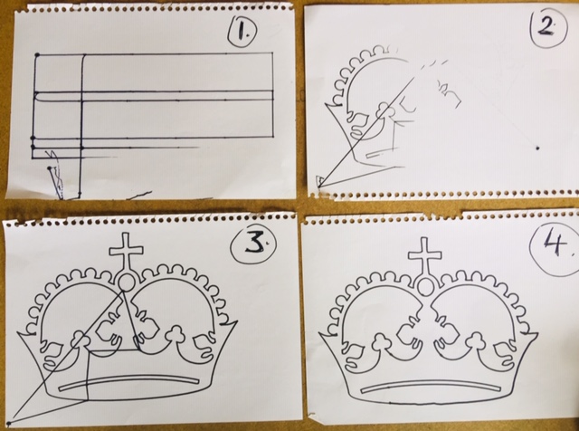
Here’ be a pic from my inital Crown tests.
I simply rotated one of the lead screw ( Z axis) connectors a few turns to compensate for the low side.
I found the trick is not to measure. Cut a piece of wood the width you want and then secure one end of the rails. Use the same wood to set your spacing along the length of the rails. Then set up your lowrider accordingly to the fence. I ended up being a little narrow and my z rails were rubbing on the table so I just put a washer behind the wheels to space it off the table a bit. Getting very good results so far in terms of accuracy and squareness
I watched a Youtube video whereby a LR2 owner cut a V grove for the wheels to roll in keeping the machine inline.
Rearding Z-rail rub - yes I have the same… I can feel it rub on one side when I push the machine freely by hand. Washers might do the trick. BTW… it’s only a very light rub, nothing signigicant.
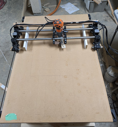
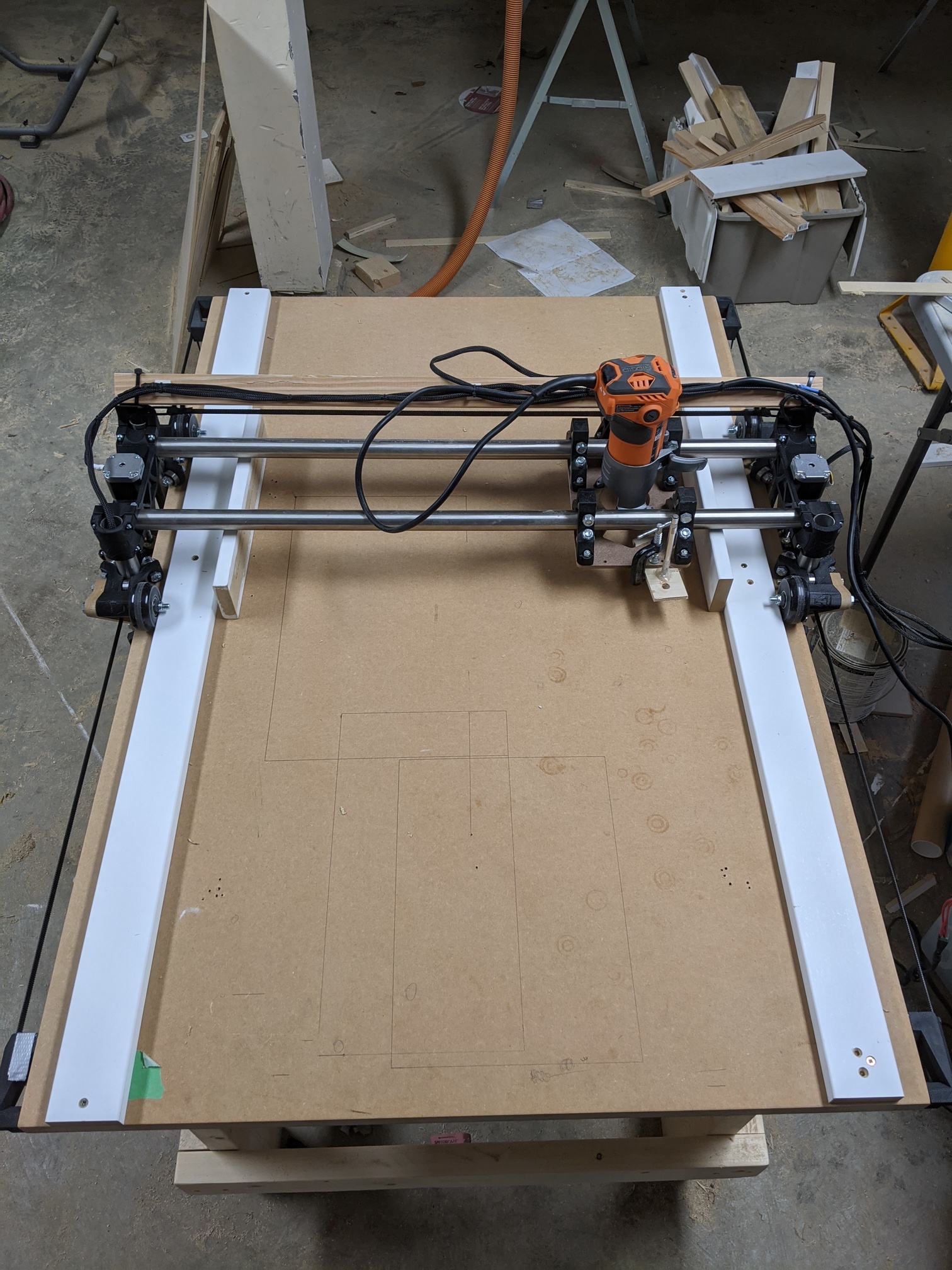
My current progress : I need to mount the power and driver boards + the TFT screen… currently sitting in a lunch box taped to the X tubes. Hope to print a housing today.
Yeah that works but they will only be as parallel as your table is. Setting up one rail and making the other parallel to it completely takes the squareness of the table out of the calculation
I just run my controller and screen on a table beside the lowrider and basically have an umbilical cord to the machine. My theory is the less stuff that is attached to it the better.
mmm… true but how about if you were to router out the V Groove against one of the hack tracks as apposed to against the side of the table. That’d do it right
Yup that would work. In my industry, grooves are just areas that collect stuff so you just have to make sure they stay clean. You would have to setup the hack tracks parallel and then use them to cut your v groove on both sides of the table.
 The board I used I found in the street… so it has been weathered. Looked good to me at the time & I simply wanted it for the inital build.