Printing is finally going well. had a few issues with inside holes not turning out. thanks to those who have offered suggestions.
Just ordered the electronics and parts. Looking forward to getting those.
I didn’t look, how long does it normally take for those to ship?
Regarding the printed parts.
Due to some issues at the beginning I feel I might run out of PLA with a few parts left to do. Just wondering if anyone would be willing to help out and print a part or two if needed. Will pay as well as shipping - as long at is does not come out to be more than buying a new roll of PLA.
Pla is pretty cheap, and by the time you absorb shipping printed parts, you might only save a dollar or two at best. Plus, a lot of us break parts on the first assembly because we are used to building things with injection molded plastic and metal, so you’ll likely need to reprint parts anyway. Just my two cents.
Understood. it also has to do with access to the printer. I’m borrowing one now and I’m not sure how available it will be later. This is probably more the issue than getting the PLA.
After calculating the amount of estimated PLA I think I will be OK.
Are there specific parts that are more common to breaking than others?
Best thing I can say is that you are not really tightening much. You can’t crank down on the connectors like you can if the pieces were wood, or metal, or even injection molded plastic. Stop often and visually check things. I found that the nylock nuts provided enough resistance that I could easily break the printed pieces if I was expecting to feel when the nut made contact. Better to stop and visually check if you’ve made contact. Most of the nuts are literally just screwed in enough to catch the nylon anyway.
tl/dr; 90%+ of parts break during assembly due to the overzealous application of manly torque.
Will there be an issue I printed the 4mm tool mount instead of the 6-32? or is it just a matter of the bolt size and will need to get some from the hardware store?
The two tool mounts just have to do with the size of the nuts it is designed to use. If you printed the 4mm one, you’ll need to source some M4 nuts and screws.
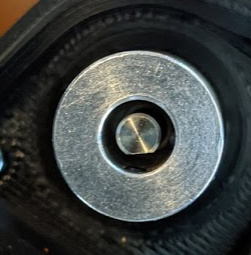
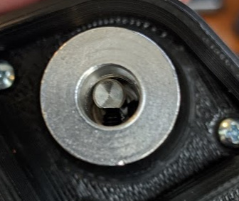
things are coming along. the table is nearly finished. I have started the Z axis assembly and am fitting the coupler onto the stepper motor but I don’t think it is right.
the coupler looks like it is too large for the shaft of the stepper.
after it is tightened
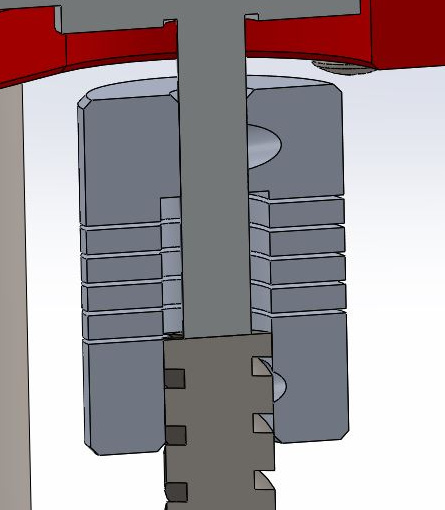
the coulper I got from Ryan does not have the same cross section shown in the docs.
The coupler is supposed to have a 5mm hole on one side (for the motor shaft) and an 8mm hole on the other side (for the leadscrew). It sounds like that’s not what you got.
First, Thanks Ryan for sending me the coupler. I failed to send a thank you email.
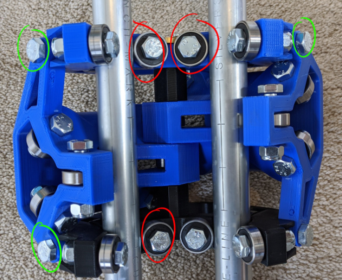
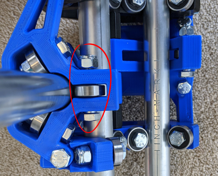
Second, I have the gantry part assembled, but noticed that a few of the bearings do not touch the rails.
The red circle bearings for the Z axis do not turn (they don’t touch the rails) - however I noticed that there is no play in the Z axis. Granted it is not under load from the weight of the router or movement.
To fix this do I tighten the green bolts?
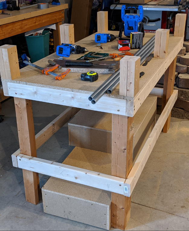
And then lastly, since this is build blog, here is a photo of my table so far.
The 2x4 risers are so I can get the 10" clearance I need. I did this with wood risers as I was afraid conduit risers that tall would be less stable.
The boxes on the floor are platforms so I can do thinner wood parts if necessary without lowering the Z axis so far.
I would start by taking the rails out, make sure all the 1.25" bolt/bearing combos are snug and the 5" bolt has both bearings on it. The large XY part should be kind of a snug fit even without the tension bolt snug.
The next step with the z axis in (and make sure the rails are parallel) is to make sure the 2.5" bolts are a little more snug than just touching (and equally so).
I know it sounds vague, and it is, but take you time and see what a 1/4 turn extra or less tension does.
If all else fails just put it together and use it a bit, then take it apart and try again, that usually seems to work.
Ryan,
thanks for the feedback.
So here’s what I did. while waiting for a response I did tighten (slowly) some of the tension bolts. That did not seem to do much so I backed those off.
Then following your feedback. I snugged up the 1.25" bolts. I noticed I that I had originally left them a bit on the sloppy side, like a 1/8 turn before there was not side-to-side wiggle. So I tightened them up so the don’t have the side-to-side and still turned nicely. This certainly helped with the X and Y axis and eliminated the slight slop I had.
The Z axis seems a bit better but still has some bearings that don’t touch the rails.
Like you said, I think I will get everything set up and run it a few times - marker drawing stuff - then re-assemble it. Break it in a bit