Hi all,
I’m yet another who has been dreaming of a reasonably priced cnc set up for many years. I was drooling over the Maslow for a long time. However I have yet to be convinced about its accuracy/reliability/consistency even though I don’t think I need more than 0.5 or 1mm accuracy across an 8x4 sheet. Anyway, I did not come here to shoot down Maslow. They are a passionate group and people make amazing things with it. Can’t discredit that.
I’m interested in small boat builds and have recently got a shed just for this. So now I’m shopping in earnest.
The question I have yet to answer about the Low Rider 2 is, how much € to build a 0.5 - 1mm accurate 8x4foot setup with a useable z axis? (0.5mm accuracy)
It seems to be a very “DIY all the way” system which has its advantages, though it leaves me with a lot of questions as a newcomer.
Can someone point me to an example build I can reference. I’m in Ireland so US builds with stainless tubes sourced in the US are not ideal. I should possibly also note that I don’t have a 3D printer. Another project for later on I hope.
I have more ideas too like being able to lift it up out of the way when not in use, but perhaps I’ll build up to that later.
Thanks for reading this long hello.
You can buy all the parts and hardware in the shop, except for the router and the tubing. There are one or two official partners in europe for the printed parts (But I know very little about shipping across that continent).
The F version should work for 25mm tubing. So you should be able to find something somewhat locally. The parts list also has metric hardware, but there isn’t any one click buy for the metric parts.
Thanks for the reply.
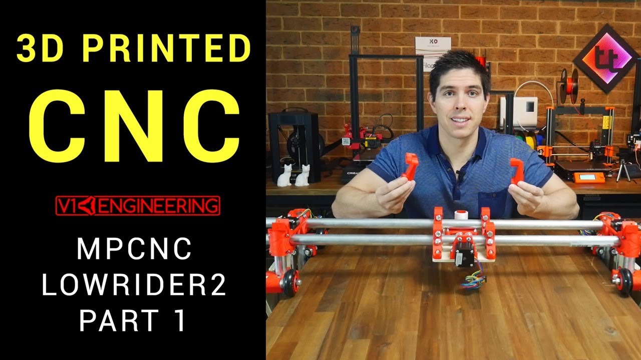
I may have answered much of what I was looking for by watching this.
I guess I’ll need to look at how to make a large table top really flat and ridged. Thinking Ron paulk torsion box thing and an extra layer of MDF. I’ll look around to see what others have used.
Yeah. Just don’t get too hung up on the table. Pretty much any table will work ok. It can’t be too thick (so a paulk style will need side rails) and it needs to be reasonably flat (so you’ll need to do some tuning on a 2x4 table).
That vid is great. The skr board isn’t what I would recommend though and his firmware doesn’t compile out of the box. A better choice is the skr pro w/ 2209s. Ryan started selling that in the shop and I expect the configuration will stay up to date.
a 5’ wide gantry is going to have some sag. if you absolutely must have .5mm Z accuracy you need to look into getting some sort of collet mounted switch and doing some sort of “bed-leveling” (workpiece-leveling, in practice) to get your Z height correct on a sagging Z with a possibly un-flat table).
rigid tables are generally some sort of torsion box, but there have been aluminum extrusions, welded steel, and other more innovative schemes. I have dreams of doing a composite laminated table (thin plywood with 2" XPS foam in between, but that is still a long way off.
Or, you can surface it with the router. But it is not necessary for a long time.
Get the bed to match the z sag 
Ok, I had not thought the tubes would give that much sag but I guess almost everything sags over enough length. I wonder if anyone has fixed that somewhere. Perhaps adding more to the gantry! Though that might impact the y response time. Humm
The tricky part seems to be
-figuring out when to jump in, (when along the research path)
-what subtle variations to choose( controller board, tubing, etc),
-and what tweaks to head for( y axis grooves, auto homing/zeroing calibration, any additional rigidity) to give 0.5 accuracy that is easily repeated.
Also I see murmurs of a new version coming!
Any new LR is at least 6 months out. I am not privy to any information that isn’t in the forums right now, but based on how long the primo took (and is still being honed). It’s not anywhere near soon. We are just daydreaming while watching our robots works and having a little fun.
Regarding sag/Z accuracy.
- You don’t need to make the gantry avoid sag. We are talking about 2-5mm at the most (and provably less, but it’s hard to measure) over 1200mm. The mdf or plywood or hardwood you are carving is going to sag a lot more than that and fit whatever the contour of your table is. If your table is parallel to the gantry, and your material is perfect thickness, then you will be have a very accurate Z.
- You don’t need a terribly accurate Z. If you are cutting out plywood furniture, or large letters or kitchen cabinets or something, you will just cut into the spoil board enough to comoensate for any error in Z. Small stuff like 12" boxes can get away with 1-2mm of overcut and a coat rack that is 8’ long might need more, like 5mm.
- V carving is pretty sensitive to error in Z. If you have a 90 degree bit then every 1mm error in Z is 2mm error in width. If you have a 45 degree bit, it is only 1mm error in width. For this reason, you shouldn’t expect to carve huge patterns with V bits. If you can, you should plan to use flat bottom bits, or else break the job into smaller jobs, and pick a new Z offset for each job. It’s not hard to avoid because large jobs tolerate flat bits a lot more anyway, and honestly carving a 4’ workpiece is going to test your patience anyway.
- After all of that, if you do really need to get an accurate Z over a large XY, and you have used the machine enough to know it will be relatively stable, you should invest the time into surfacing the spoil board. Taking that 2-5mm off with the router will mean that your plywood will sink into a surface that matches the shape the gantry moves in. It is simple conceptually, but I would still encourage anyone to wait. If you surface the board and then find an issue and change something, you may get a totally new Z offset and you’d need to surface it again.
I have been meaning to redo my low rider table and what I want to do is build a frame and use the LR to flatten the supports under the spoil board, and then attach a spoil board onto the now flattened frame. The frame will take a fraction of the time to flatten and when I replace my spoil board, I can do it again, or just keep it how it was.
If you are not already doing it, consider flattening one side of the dimensional lumber before assembling the frame. When I built a new table for my Primo upgrade, I screwed angled aluminum to to the side of the support boards and ran them through the table saw to create a flat edge. Not a complete solution, but it might greatly reduce the time it takes to surface the boards. And the boards will probably move some no matter how accurately the surfacing is done.
Really appreciate all the info. All good things start with dreams ![]()
![]()
Research is still evolving my views on it all.
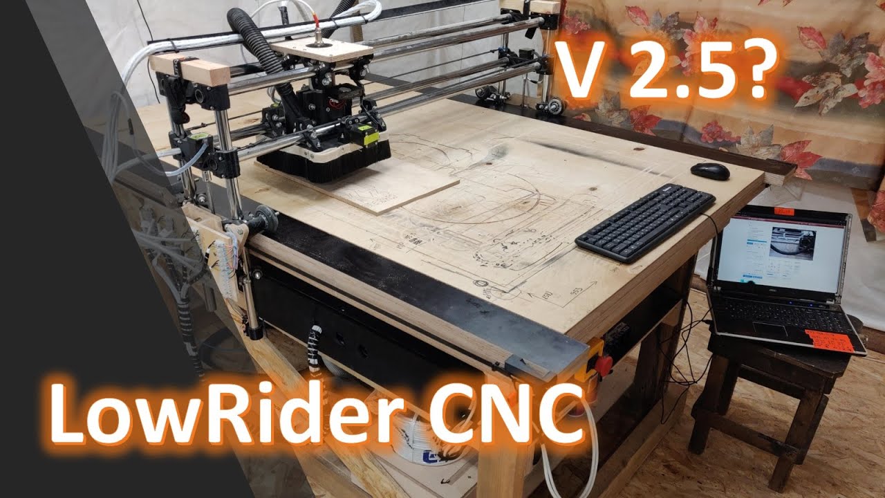
This guy has resolved a few things.
Have yet to check how much this deviates from the kit bundles.
V grooves for Y and bigger Y plates with additional under rollers too. He might christen it the “KZ High LowRider” @kzdesign. Thanks for the info.
I liked the auto axis zeroing from Michael at Teaching Tech. Have to figure out if that mod is something only possible on a selection of boards so as to not have to buy another board later on as I later look to upgrade an initial build.

