it is indeed a nightmare to model, i tried a couple times but lacking accurate measurements it never came out usable.
For the most part it is two different sets of arcs on each side to form sets, or matching on each side, it is not two different sized circles like you would think. From there it has a massive draft angle. I think the real issue is they do vary so my mount grabs the fixed part that is made for mounts, and the other side grabs near the rigid motor (but does not need to be very precise).
It is a hard mount to model. If you can use the bottom of mine and use some of the built in screws.
yea, i made a poorly thought out dual tool mount that is basically your upper-lock piece with an arm, but right now i am trying to model something like a quick-release system, and i want to make a “sleeve” that goes around my laser so they fit the same mount.
Out from left field you could try some of the 3d scanning apps on the iPhone - for example Trnio (no I haven’t tried it yet). They claim to create 3D models from combining photos. Looks like they produce an STL file.
With an STL file as a reference, you could pull it into onShape (likely other CAD tools to but I have done this in onShape) and then use the corners of the stl triangles as reference coordinates to build sketches - like slices through the DW660. You could tweak (sounds like a lot of work) these sketches using real world measurements. Once happy with the sketches you could then loft between them to create a 3D CAD model. Sounds easy - insert all sorts of CAD details in here.
I turn bowls in addition to this CNC stuff. Was playing with the idea of using this software to model the bowl so that I could then CNC inside it or the bottom/outside. Lots of software to write to make that happen. At the moment it is an idea and not reality.
After you asked, I though a model of the DW660 would be a good Fusion 360 learning exercise for me.
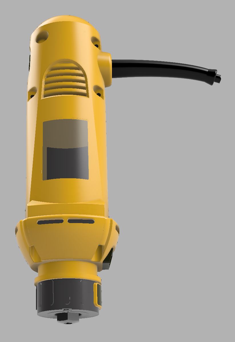
I used calipers on the overall body, but some the details were done more by eye, so they will be less accurate. Of course given Ryan’s assertion that real world routers vary in dimension, I’m not sure how good this model will be for creating 3D printed parts. A ZIP file with a STEP and an STL file is attached.
Dewalt DW660 v43.zip (2.4 MB)
8 Likes
this is awesome. you should post this on grabcad - i’m sure it will help a lot of people.
Good point. I’ve used many models from grabcad in designing things, but I’ve never given back. So I just published this to grabcad.
3 Likes
i have to say, i have been astounded with the level of support i’ve gotten from this community. i’m no n00b, but i’m definitely not an expert (a bit of a jack of all trades - so i’ve mastered none). anytime i haven’t been able to dig up an answer for myself i’ve turned to this community and i never leave without a better general sense of what i’m doing. i’m guess what i’m saying is : thank you for all your support.
3 Likes
It definitely looks neat 
Looks like you are cruising right along with fusion, Robert.
Well, I’m impressed!
i can attest to the accuracy of this model as compared with my actual router. i modeled the pieces to replace the end cap without the use of it, and my pieces fit robert’s model just as well as they fit my router, so again mucho appreciado.
1 Like
Ok, when is the F360 master class? That is some learning project!!!
2 Likes
i know right? @robertbu: you know youtubers make money? it certainly seems like you have an audience all lined up 
1 Like
Now I am even more impressed. That is a very hard model.
Thank you everyone for the kind comments. Jessie: no interest in making videos (that’s a skill by itself), but I have to say that everything I’ve learned about Fusion came from YouTube. There is a lot of good beginner content on YouTube, but not a lot of intermediate content. For anyone interested, I bumped into this YouTube channel recently, and it has revitalized my interest in progressing with Fusion 360, and some of his design and Fusion 360 techniques were used in the DW660 model. There is some basic content on his channel, but all the recent stuff is more aimed at intermediate learners…and he does a beautiful job of compressing the content.
2 Likes
very true, i meant more to be humorous than anything but i am definitely gonna check out that youtube channel, that’s where i learn most things as well.
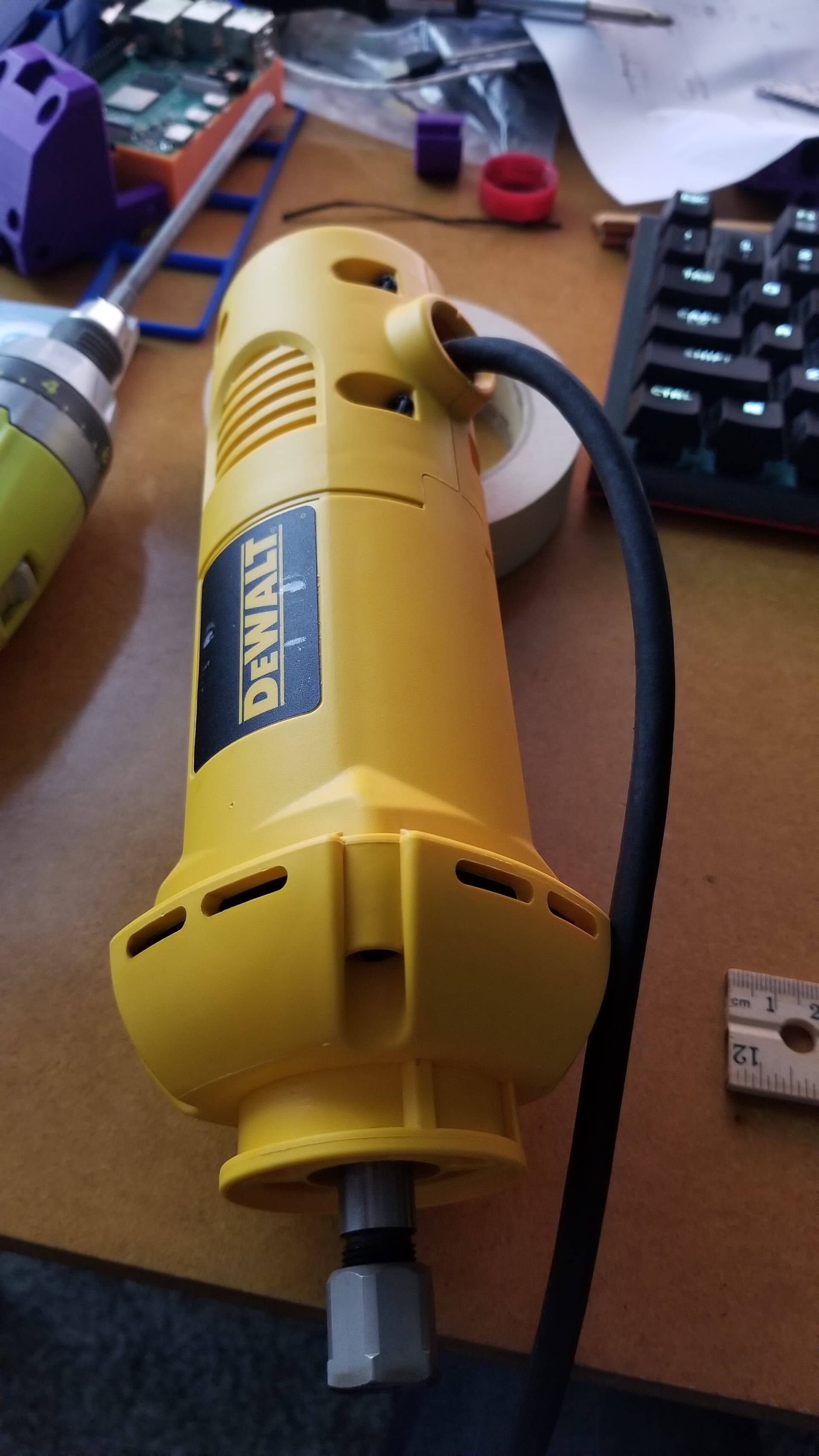
First, thank you for your work in creating this model. It shows a lot of care went into matching all the features.
I’m seeing one discrepancy in the body shape, where the sticker sides which have the air intakes are a bit narrower, and the other two sides with power cord and switch are wider. And both are barely tapered.
But in this model I am seeing it where the cord and switch sides are narrower than the sticker sides as it approaches the square front exhaust piece. The sticker sides have a significant widening taper from the back to the front, and the zig-zag meeting corners appear to go the other way.
It is subtle and easy to miss visually, and it’s possible the routers are different. Can you double check if your router is like mine?
In particular, on my router the “crease” is to the left (closer to the sticker) where it approaches the front square corner.
The model has it going to the right:
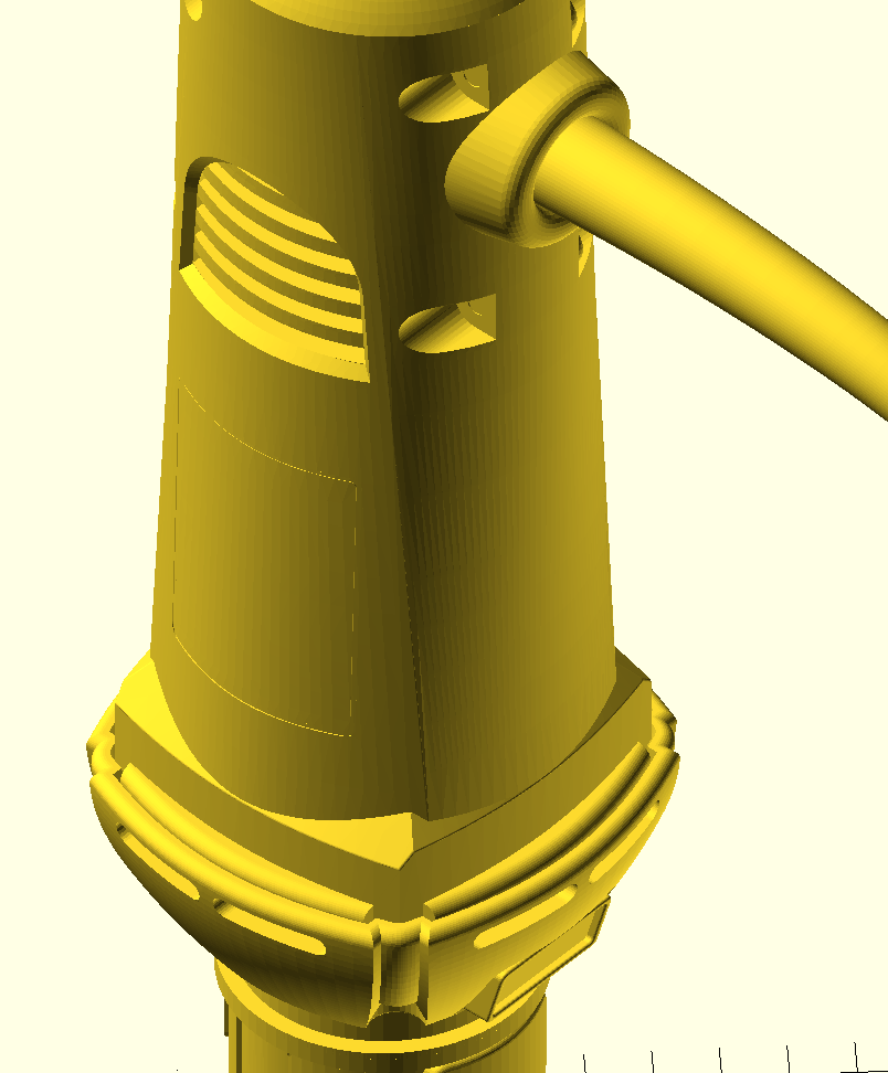
1 Like
I’m away from home but will be returning today. I’ll check tonight.
1 Like
You are absolutely right about the issue. I wrote, “some the details were done more by eye” in my original post, and I remember struggling some with the vents and stickers. I see now that the problem was with the base form. I don’t have time now, but I’ll see if I can rework it tonight.
Thank you. No rush. I’m moving forward with my scanning approach since I will need that anyway for my angle grinder and who knows what else later on.
1 Like