Howdy gang,
I’m trying to assemble my first MPCNC and having an issue that I couldn’t find referenced in the search anywhere.
Some portion of my build appears to not be sized correctly.
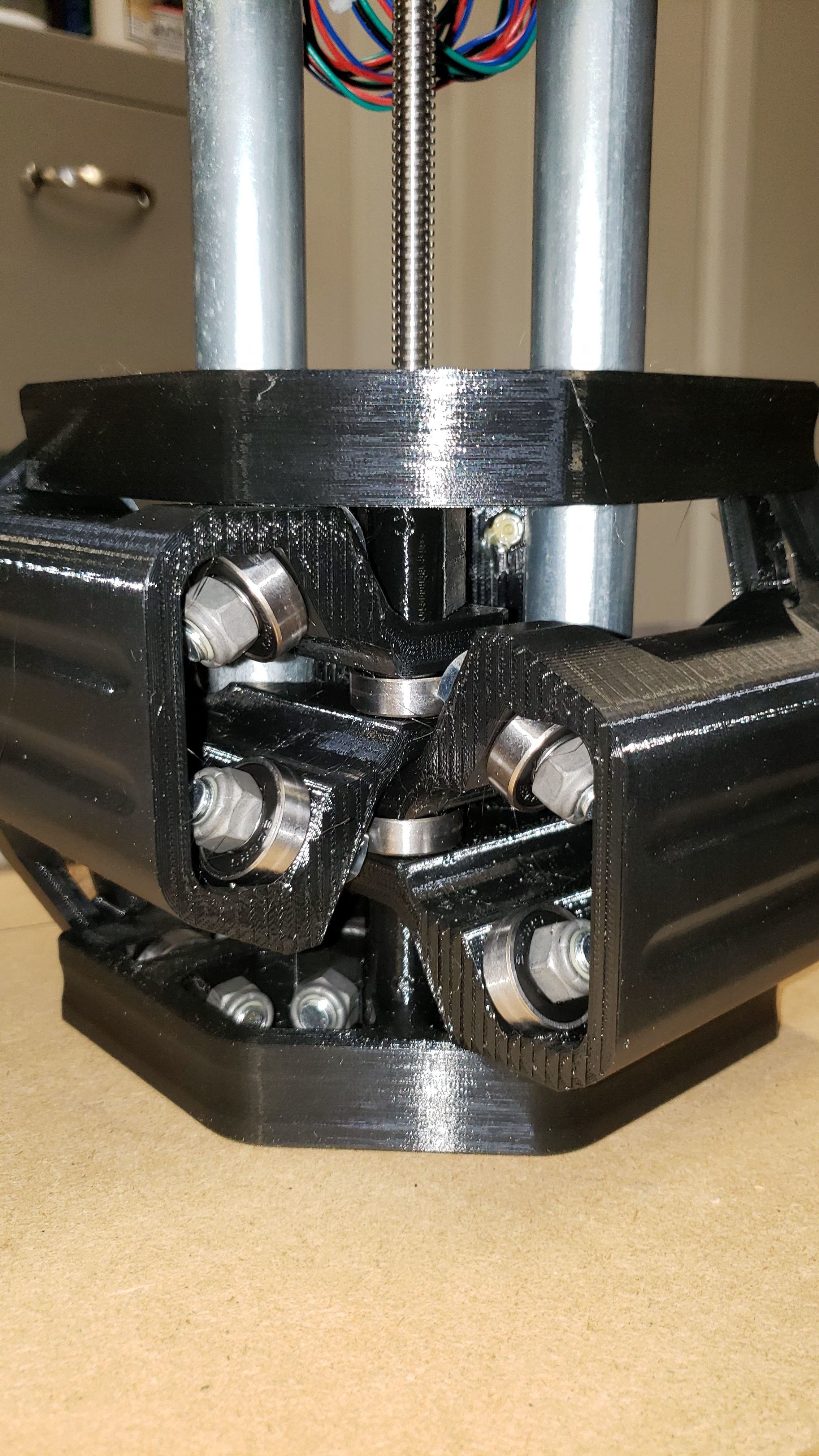
When I am attempting to install the center carrier onto the 4 rollers that run up and down the X and Y axis, either the lower set of rollers are too low or the upper set are too high.
If I install the motor mounts onto three of the four rollers, the last roller (on the bottom rail) is about 6-8mm too low if the center carriage is pushed all the way to the other end of it’s travel and about 2-3mm too low if the center carriage is moved up close.
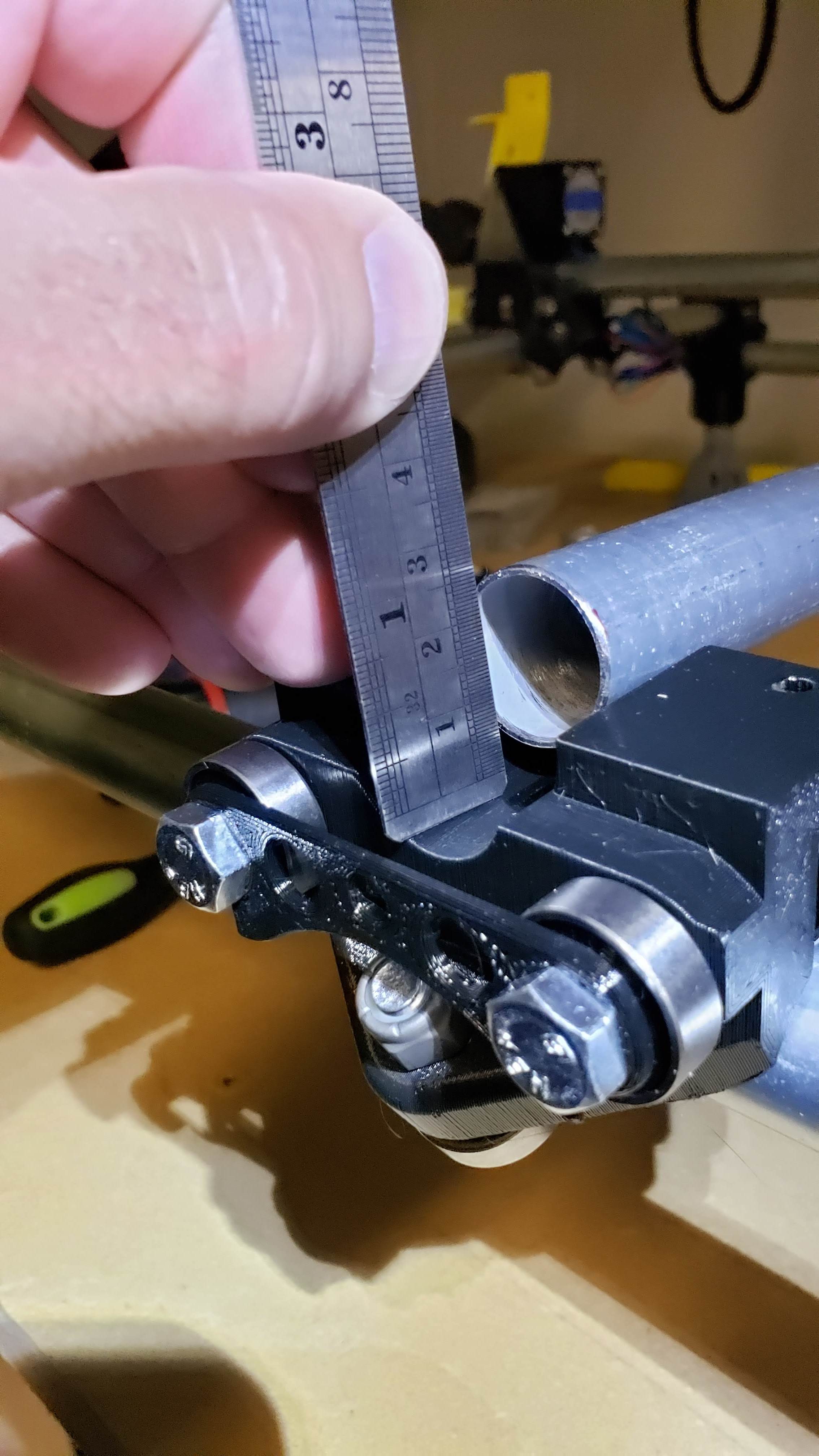
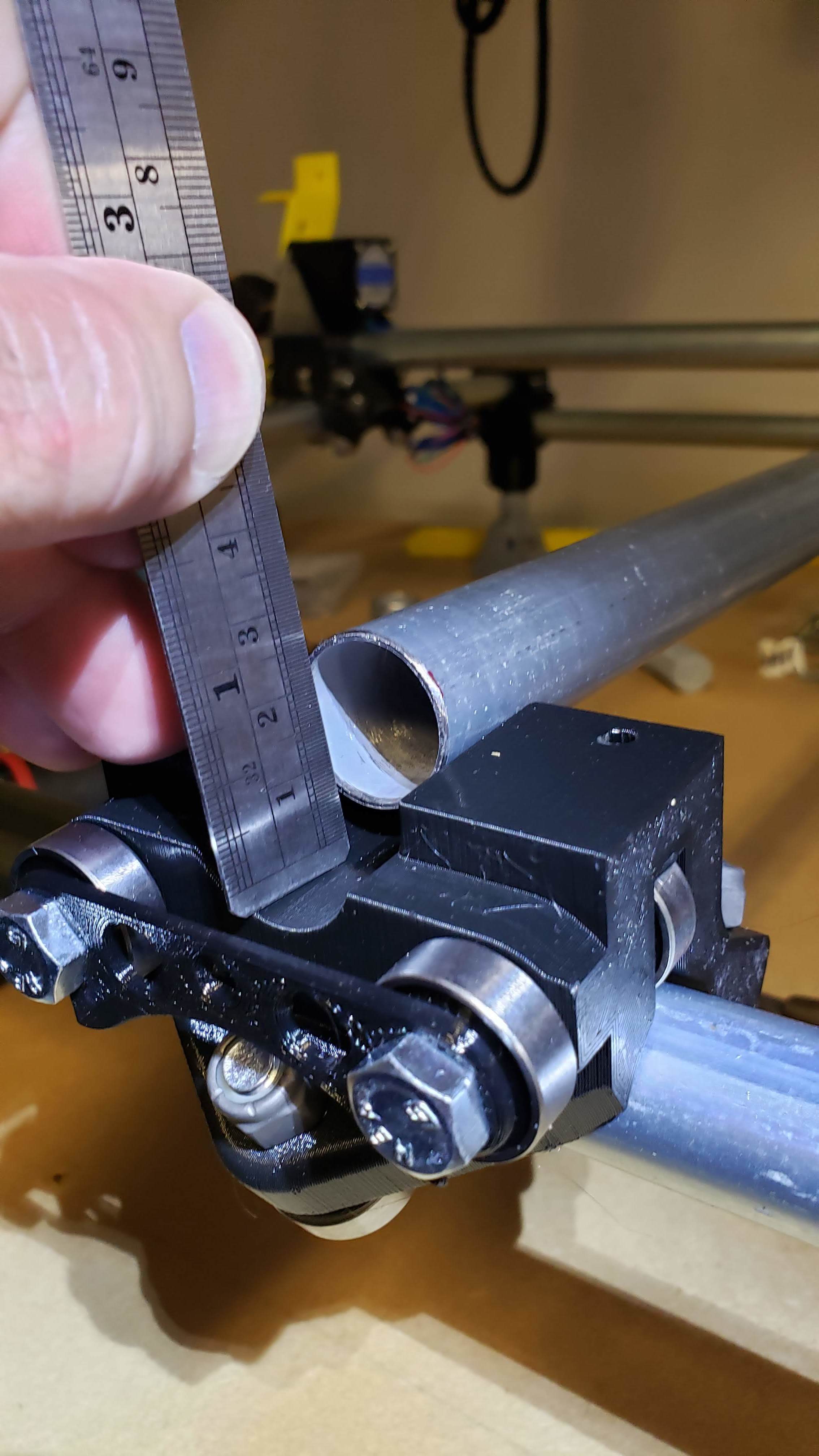
I’m attaching some pictures to see if those are any help.
Can’t you just rotate it on the pipe so that it properly fits?
My roller rotates on the pipe while moving it along the respective pipe. But when everything is connected and fixed its working like it is supposed to do.
I think you are right Brian, hold the pipe and the loose carriage and roll them up and down the rails a couple of times and the pipe will seat itself as the carriage fixed to the pipe rotates a bit.
I didn’t do a good enough job explaining the problem it seems.
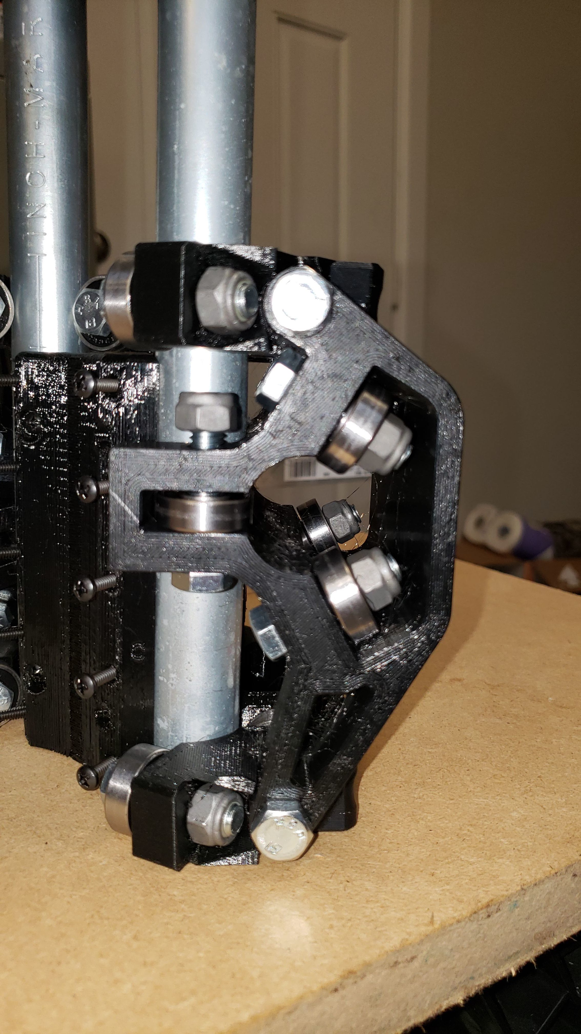
Unfortunately the issue isn’t that the roller is not square to the pipe I’m trying to mount, but rather that the roller in the picture is low enough that I would have to bend a bow in that pipe to get it to line up.
It seems that either my x-axis and y-axis are too far apart vertically by several mm, or the center carriage has the x-axis and y-axis too close together.
I really don’t see how an issue with the center carriage is possible given how everything lines up and fits together, but I’m equally stumped as to how I have managed to mess up the x-y axis mounts.
At least whatever I did was consistent as I get the same misalignment issue regardless of which end of the y-axis I attach first.
Certainly sounds like something is out of square/plumb/true.
I agree, I’m just not sure what it is that I’ve gotten messed up.
1. Are you certain all of your rails are straight?
I think so. As straight as I can verify with a framing square. If they aren’t straight it will be by only a small amount as the look good along the ~24" side of the framing square.
2. Is your table flat?
The table is pretty flat. I built on top of a new piece of particle board, knowing that particle board is generally pretty flat. Also, the table looks good when I check it with the framing square.
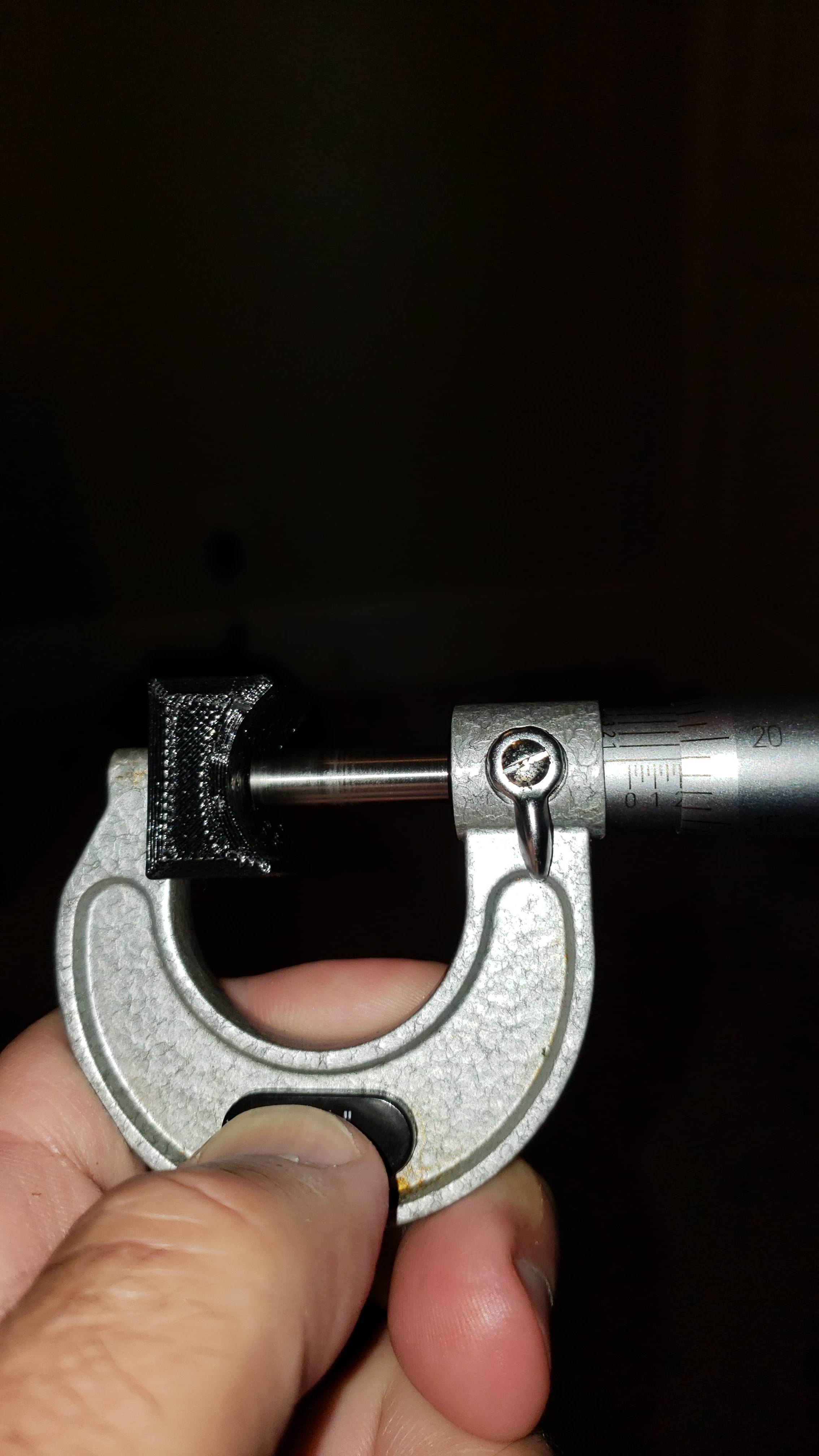
3. Are the feet all the same height?
Within .3mm
4. Outer Rails all the same height from the table in the corners?
Also, within .3mm
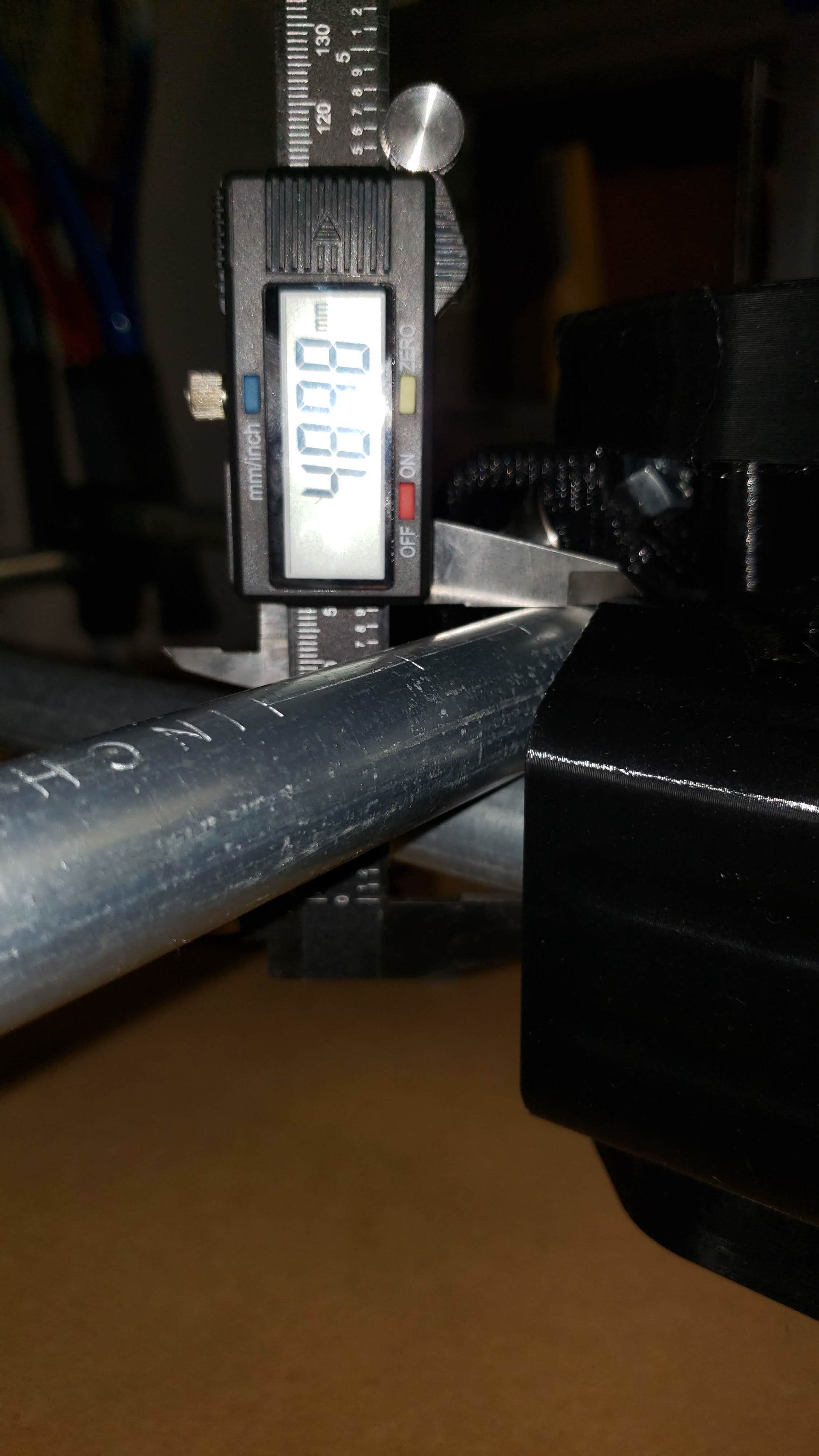
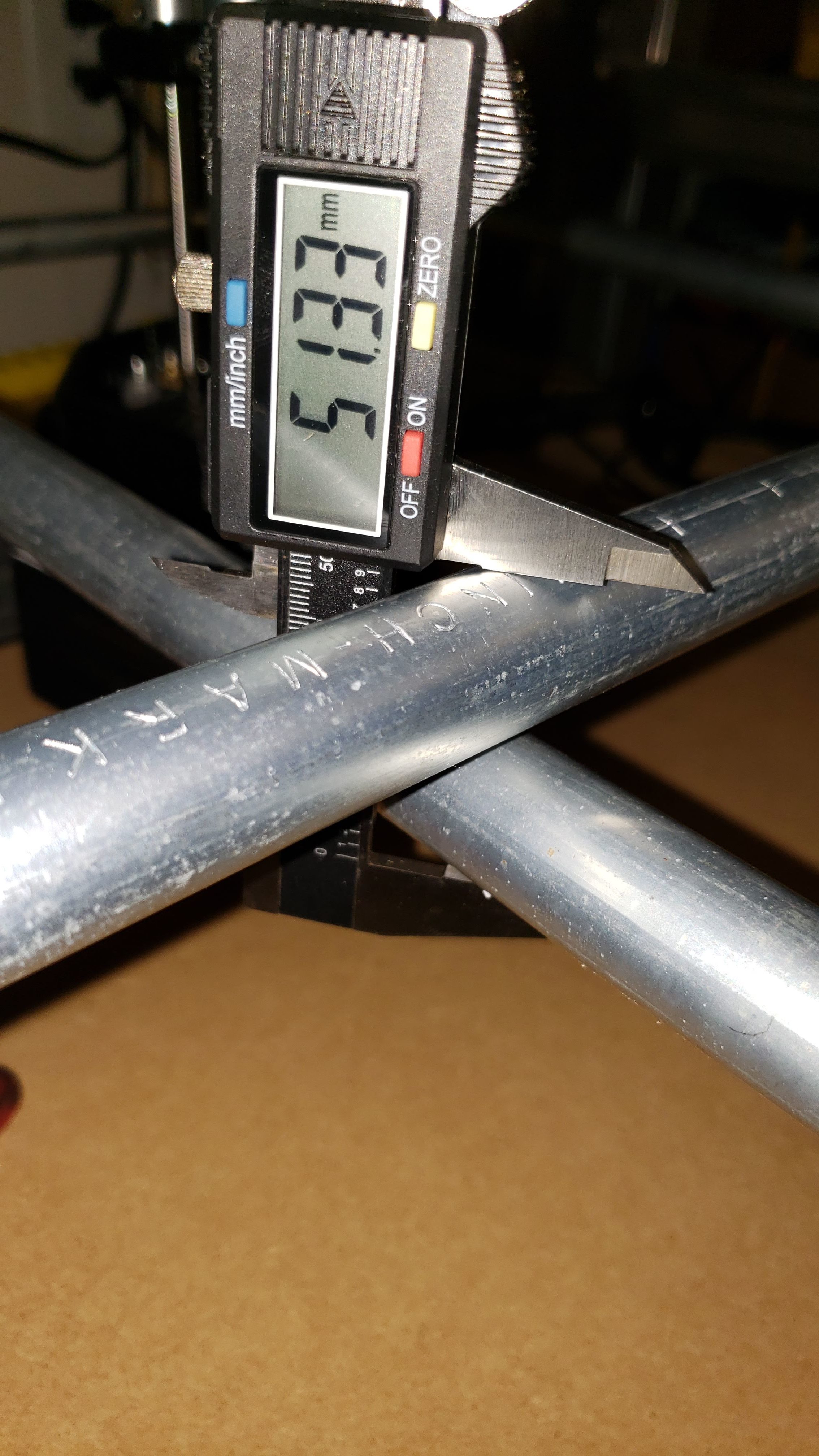
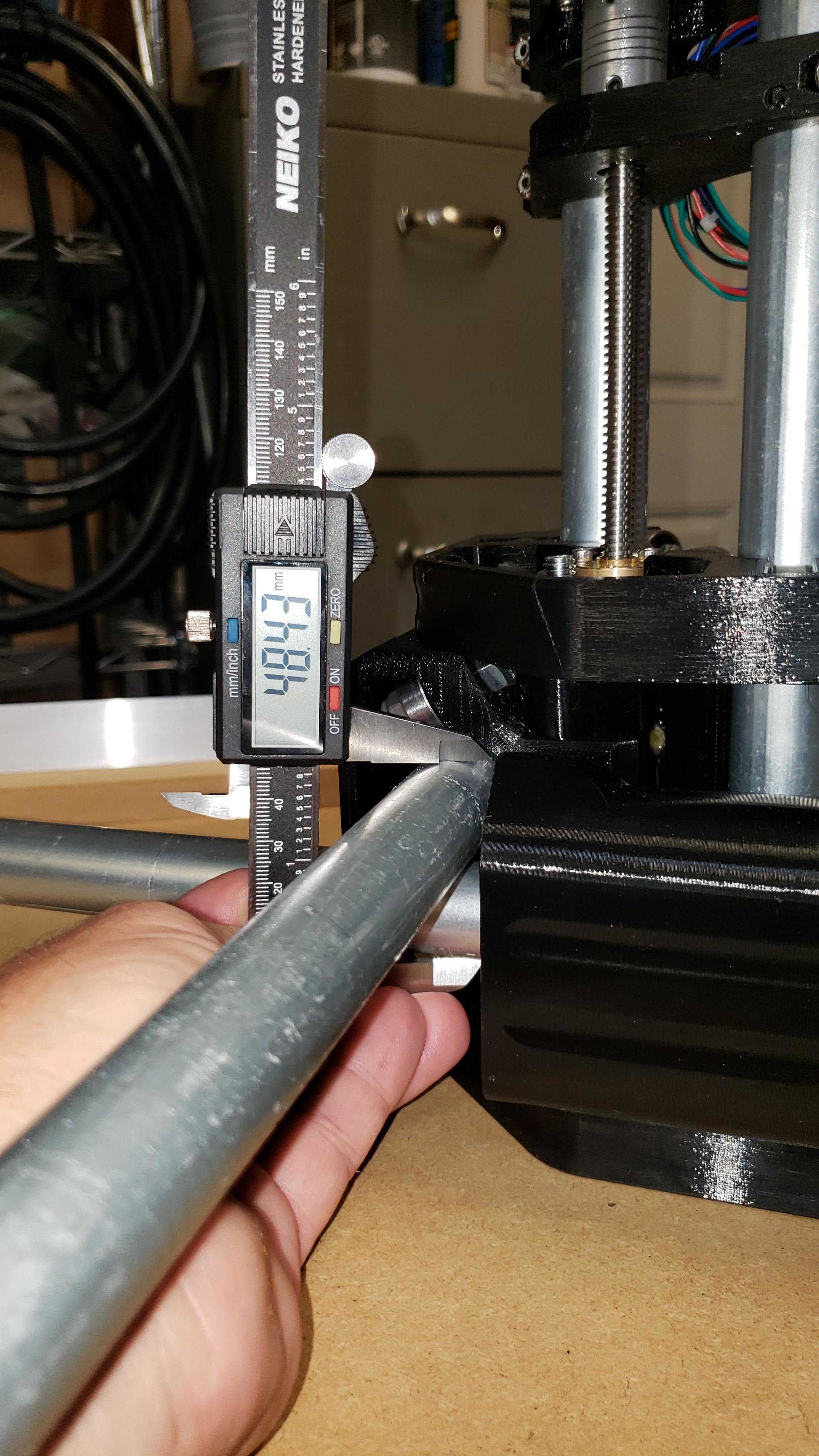
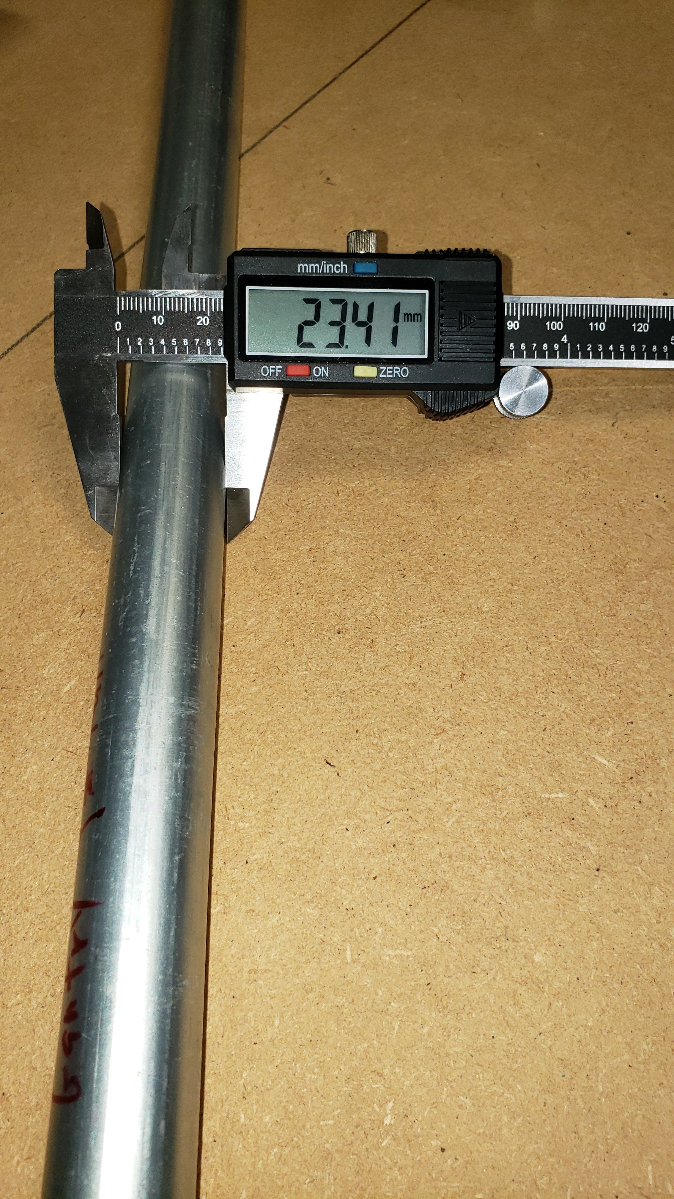
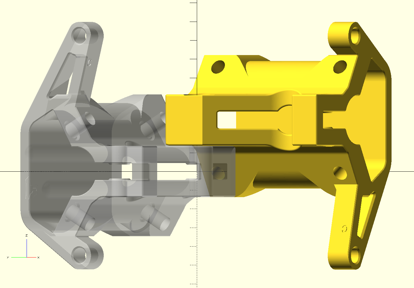
I think something is wrong with your center assembly. By my estimates, 51mm is the correct spacing (assuming your conduit is truly 23.5 or close enough) and 49mm is not correct. So the rails without the center are okay and the center assembly is improperly squeezing it somehow.
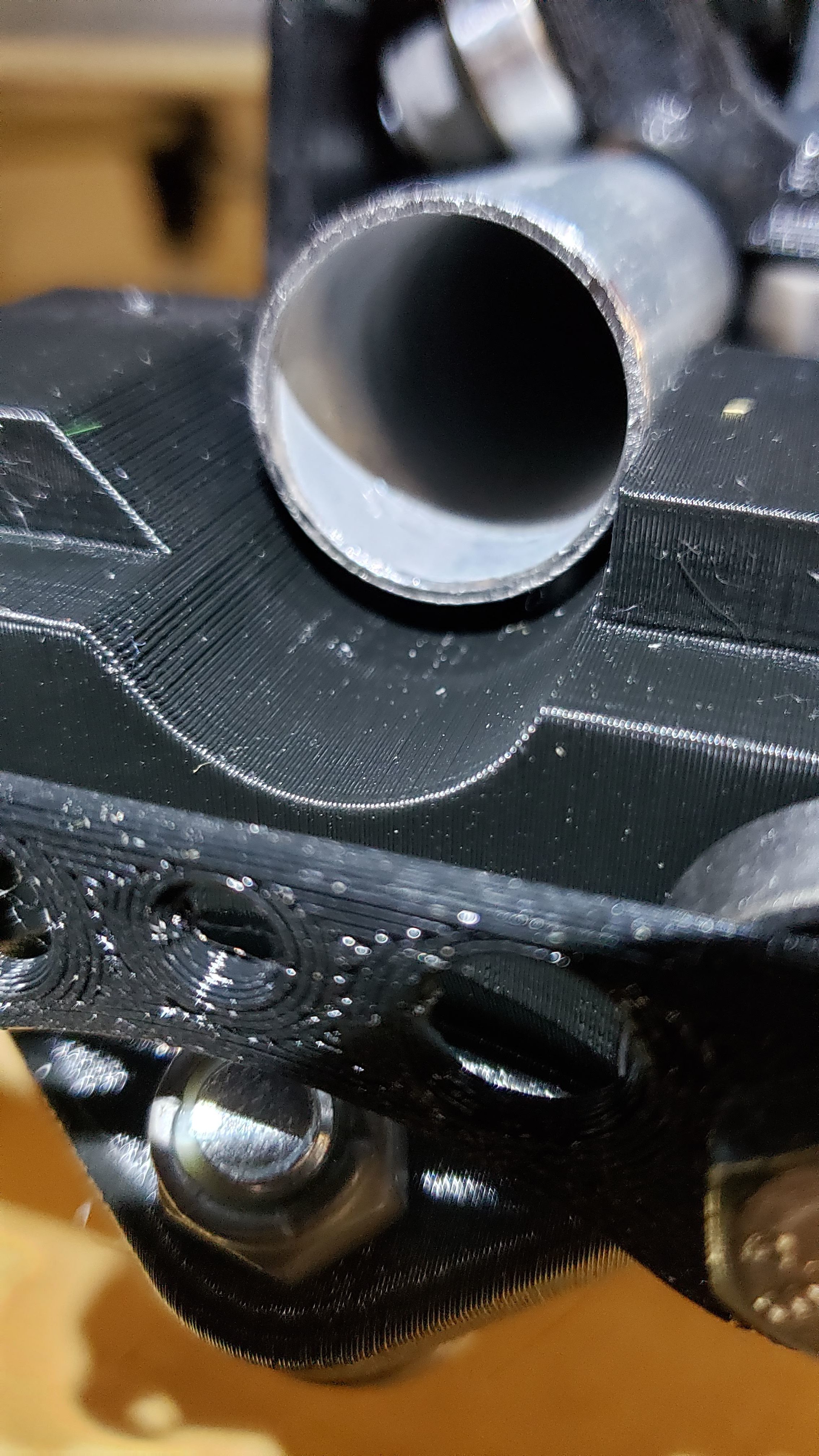
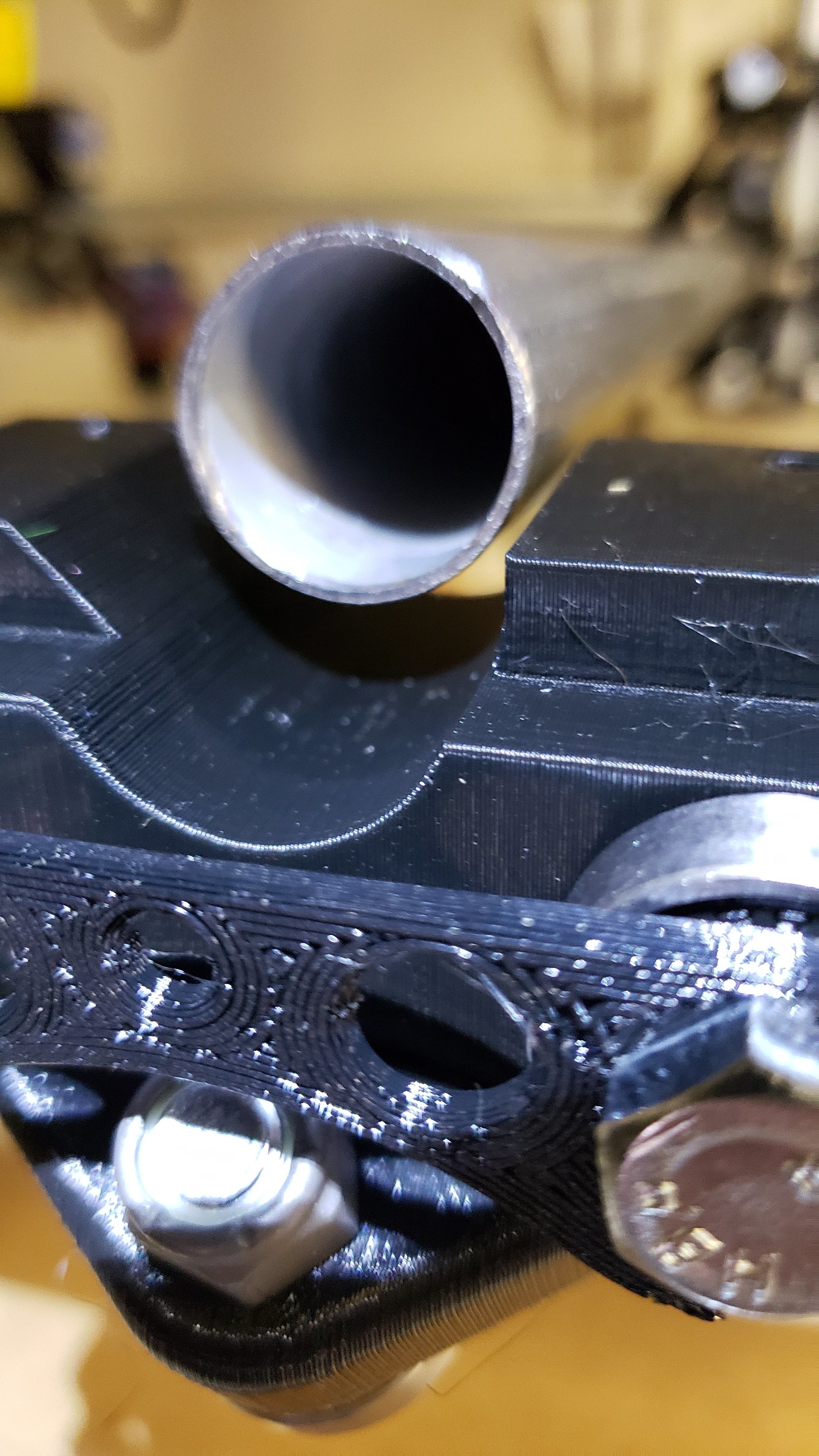
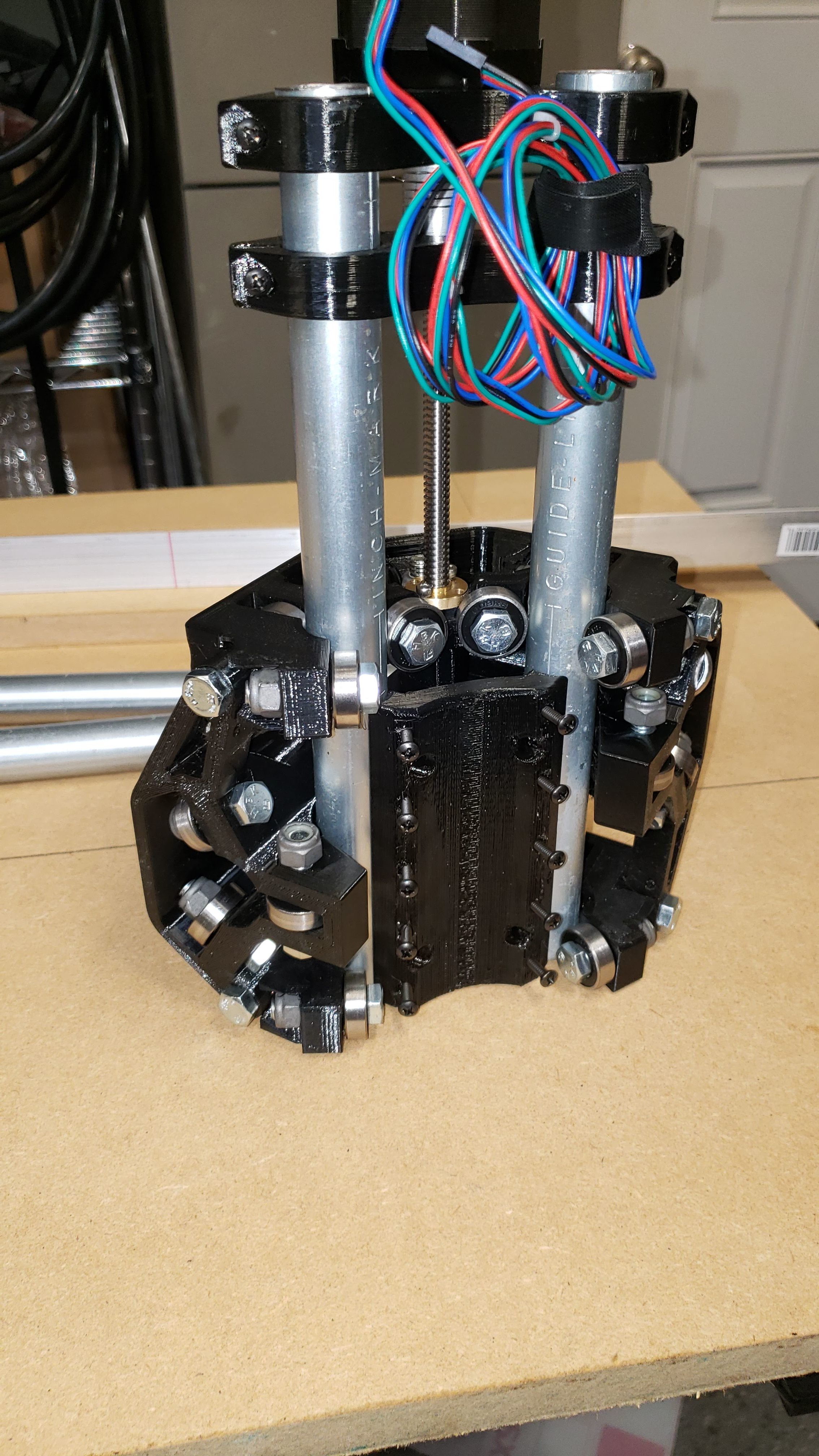
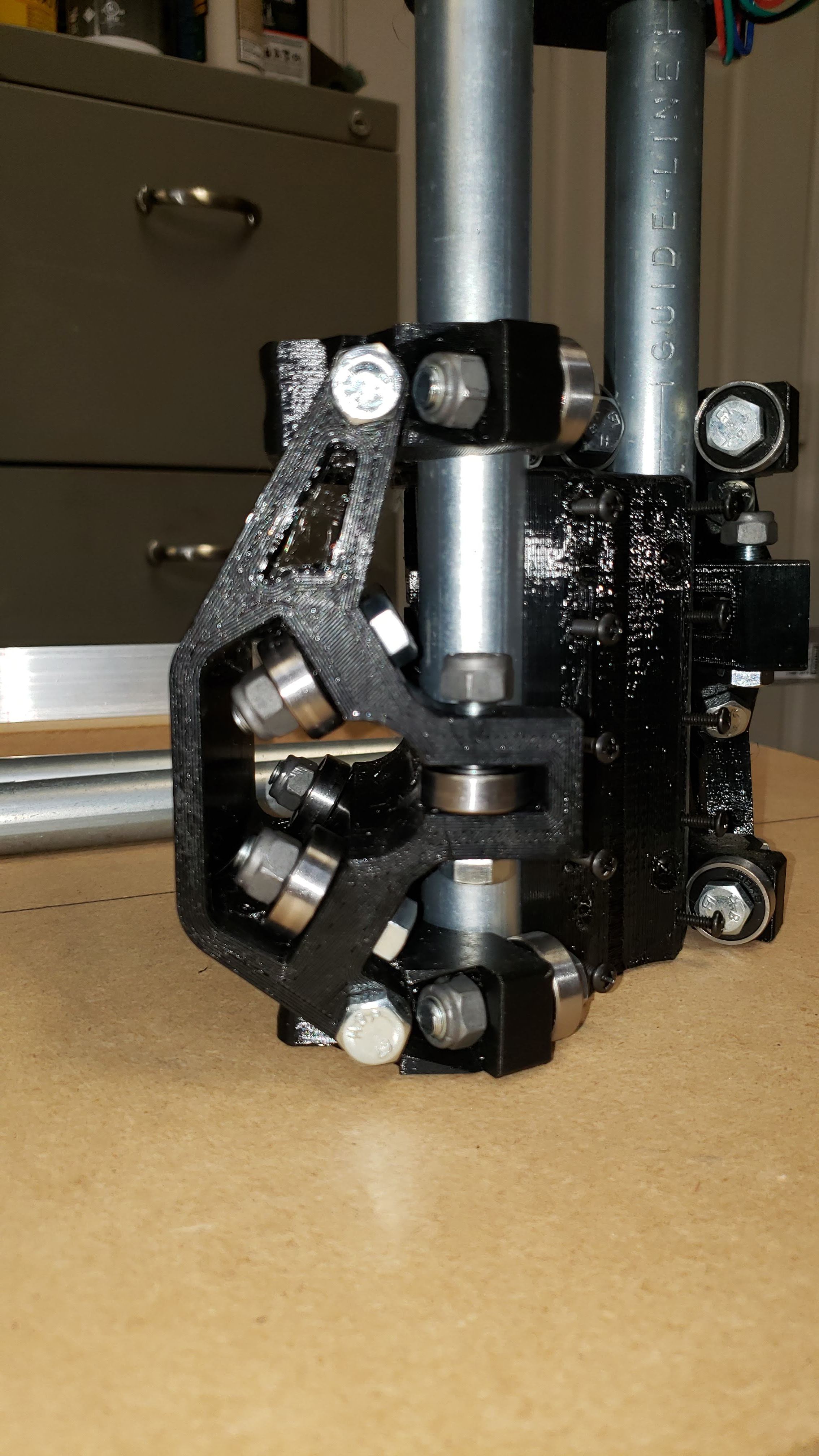
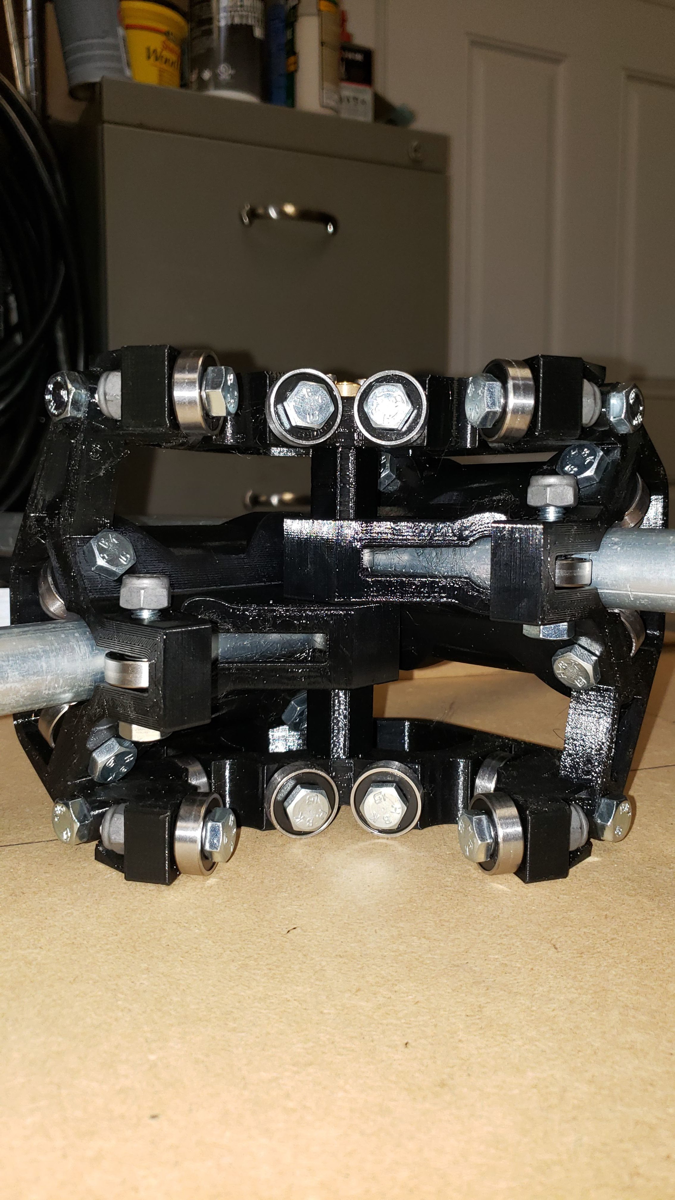
Can you share a good picture of your center assembly?
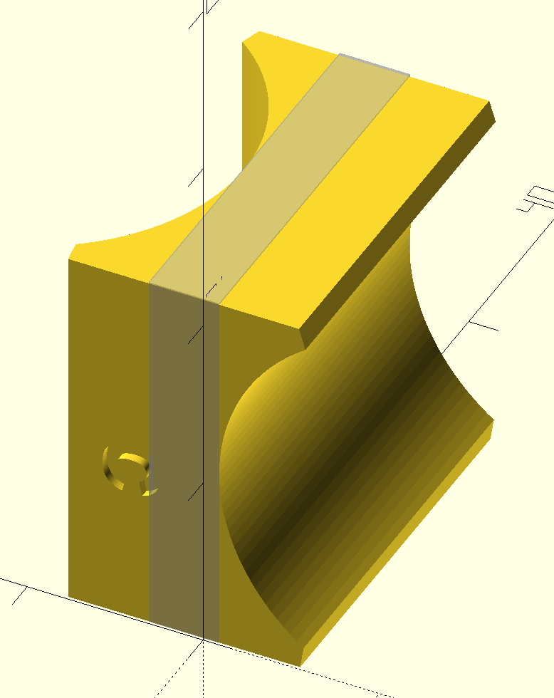
I measured (virtually) the corner spacers, showing 4.0 mm of space at the corners, which should translate into a 4mm gap between the rails at the center (since all the rollers are the same height).
This is why I’m saying the measurement should be 51 (23.5 + 23.5 + 4). But what I don’t know is why you are seeing the center assembly squeeze together. Nothing appears wrong in the pictures.
You can roll them on a surface and see if they are wonky. IDK if you’ve ever seen someone roll a pool cue on the table to see if it is straight? The surface won’t be perfectly flat either, but if they are always touching on the ends, and not the middle, then the table is sunk in the middle, and the tubes are flatter than the table.
It might fix the squeezing of the rails but I would be concerned that it could throw everything else out. It might never be square and it might be wobbly.
Another possibility is to reduce the corner spacers to 2mm instead of 4mm.