Over the course of the last few jobs I have run, I have noticed a big problem with part sizes off the machine. I am constantly off by .015-.030". Uniformly, all interior features are too small, and exterior features are too large. The amount of over or under-size condition is constant regardless of features size (for example, a 3.00" hole may measure 2.980, whole a .332 hole measures .312, both .020" small)
My machine is 2’x4’, but I am working in the corner. Ive confirmed all bolts and grub screws are tight. I checked a commanded move vs actual with a dial indicator and its perfect. I know the limitations of the design, and not to expect too much, but I have had much better results than this before. I have nailed 1" brass discs to well within .005". Something has changed, but I dont know what.
Is this amount of “slop” in the gantry normal? Try not to pay attention to the test indicator (which has a .008" travel and maxes out when I push the tool). It seems to me the entire gantry is moving. Is it pipe flex, belt stretch?
EDIT: Also, the code is good. I did the trig on the G3 moves in the code and its commanding the tool to the correct position.
EDIT 2: Also want to mention that the most recent jobs I have run in which I am seeing this issue were 1/4" birch ply with a 1/8" 2-flute mill. 40ipm rough, 20ipm finish. .063" DOC. .005" finish pass @ full DOC.
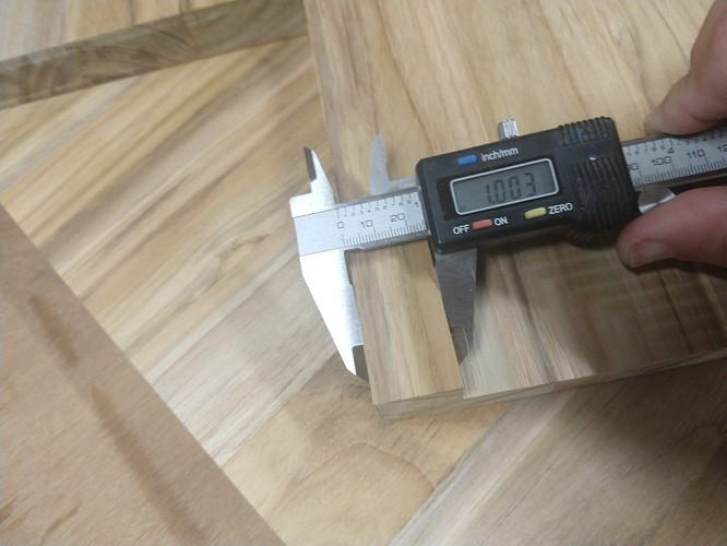
Even taking supposedly identical bits, I get varying widths of cut. My current one is nominally 1/8" but taking calipers to the actual cut, I get a hair under 3mm. I’ve got it defined as 3mm in Estlcam right now, and I get tight fits
Are you using climb or conventional milling?
Climb milling does like to pull away from the piece, but I’ve actually found it to be more accurate with a finishing pass.
When was the last time you checked your bearings for good contact on the rails?
After all, these are 3D printed pieces, and they do change a little over time. I’ve had to tighten all of my trucks to keep all of the bearings in good contact with the rails, and I’ve had to tighten a couple of the core clamps for the same reason. Not getting good contact will allow more movement.
Kind of basic troubleshooting, but maybe one step above “Check grub screws.”
The bit I was using mic’ed at .1235. Cutting edges looked good at 30x on a stereo microscope (I brought it to work, lol), no chipping. That said, I do have other bits, and that is what I will try next.
Climb milling.
Checked the bearings last night. A few were able to spin, so I tightened them up. Havent cut since, but the amount of perceived play when pushing on the tool didnt seem to change much.
Its funny, right after I posted this morning I saw a few other active threads citing the exact same material condition (small interior, large exterior). Most seem to just comp their code, or play with the tool. Looks like im not alone, but I thought i would ask first.
I am working on a power drawbar setup for my manual mill, and I was gearing up to cut 1/4 aluminum plate with the MPCNC (these pieces of ply were, in fact, prototypes). I wonder if I should abandon that idea. For a one off job I could probably compensate for the deflection to hit tolerances, but I dont have but a few plates of material to work with.
Last night I cut a part with the same tool, material, and settings…except I left -.010 “stock on” (deeper radial cut). The resulting part was pretty much perfect on every feature. This is a fine solution for cheap material, but I wonder how consistent the “flex” will be for other materials?
That’s called a finishing pass. The rough pass has a lot of load on the bit. So the bit (and the machine) flexes during roughing. The finishing pass just kisses that material and even though you left 0.010 on, it may have cut 0.02 or more of material left by the roughing pass and flex.
If you want precision, you need a finishing pass. I think that is mostly true even on the very expensive machines (but the definition of precision is different).
Thanks Jeff. Sorry, as I re-read my original post I left this information out. I am cutting with a .005 finish pass AND a .000 “spring” pass, and still ending up off. I always use finish passes, however I always finish at full DOC. For 1/4" birch (and you know it is really more like .190"), I wouldnt think that would matter. Should I be finishing each pass separately? (in other words, for each DOC stepdown, rough and finish before moving on.)
All units are inches in my head and in my posts…cant turn it off, lol.
Yes, to your question. I use a .005 inch finish pass to whatever my target is, following by a .000 inch spring pass.
The part I did last night, I moved my TARGET .010 inches from part nominal (in other words I had to OVER cut each edge by .010 inches). However, this still included the .005" and .000" inch finish passes.
Well for my two bobs worth, I cut a whole pile of different shapes and tests and things and in the end to make sure things fit without over thinking it I just factor in some offset in Fusion 360. I make the wood/ply “thicker than it is” and then I give an offset in the other axis of 1mm. Holes cut small and I just start big if you follow.
(they have changed the offset command location in the latest version of FS btw)
Then the glue will fill that 0.25mm …
Holes always cut smaller than needed. ie if it is to be 100mm across I will get 99mm. Pretty good across 1200mm of ply etc.
I spent far to long getting obsessed about the last 0.05mm of sizing.
I did this spreadsheet to try and get to the bottom of it too.
But at the end of the day I have had the most trouble with loose grub screws. I always check them now if there is any dramas.
You have learned well. It sounds like it’s time for you to get keys to the executive washroom. (Don’t get too excited, it’s the same as the normal one, but we have a slightly out-of-date McMaster-Carr catalog in the stall, and the paper towel dispenser is usually stocked)