Just finished wiring up my 8x4 lowrider and realized that as designed it wants to run in portrait 4x8 orientation vs landscape by default.
Is there a quick fix in firmware to turn the table so that 0,0 falls in the bottom left corner if facing the long direction of the table. X is left and right. Y is forwards and back?
Another benefit of switching is that my laptop screen where I layout my cuts, is “landscape” in its aspect ratio, so to have X be the wide, long axis on the LowRider, means I can design with wide content going in the wide direction of my laptop screen, which reduces scrolling and generally makes my life easier.
The LR is kind of “like that” because we like to put the control LCD on the side of the gantry…
I still find it MUCH easier to adjust my mental picture of the machine to match the layout.
There are 2 components. One is to adjust the X and Y axes moving the drives so that the machine calls them differently. This is a firmware adjustment, and is not trivial, but also not terrible. Change the dual Y drive to a dual X drive isn’t too bad… Then the real problems begin…
The LR3 is designed to home at min X and min Y. If you swap axes, this will either become max X or max Y. You cannot simply leave the homing coordinates the same If you do, when you cut, you will end up with mirror imaged pieces. This is going to mean that after homing, you are going to want to make the machine do a long jog across the table to get to a reasonable home position to start your cut. It was pretty much at this point that I decided that it would be easier to just keep my mental image of the machine correct rather than try to adjust the machine.
I suppose that you could mirror image print the core, dust collection, XZ plates, and X belt tensioner, probably also the rail riders and bearing wheel pieces to change the X homing direction of the machine, then mount it facing the other way. This would allow you to home at the new X min and Y min. (You should not need to mirror print the Makita tool mounts, but I don’t know about other spindles if they’re not symmetrical.)
I suppose that you could also probably just re-engineer the endstop switches to be at the back of the machine, instead of the front as they are, but that seems like a shame when there’s a very nice solution already there.
I understand wanting it different. It is a fork in the road. There are a few changes that need to happen. Enough that I haven’t ever thought it was worth it to support both. The first LR made that XY convention, and we have stuck with it. I’m sure there will be people who would want it the other way if we had made the opposite decision (but we could argue how many would be in each camp).
If you wanted to do it:
You do need to change the firmware to use dual X instead of Dual Y. It is mostly easy, if you can already build the firmware.
If you want dual endstops (and if, not then it doesn’t matter). You also need to rotate the gantry by 180 and make the X have an endstop on the other end.
Not super simple. But also not roclet surgery.
I don’t see a good enough argument to flip them as the default.
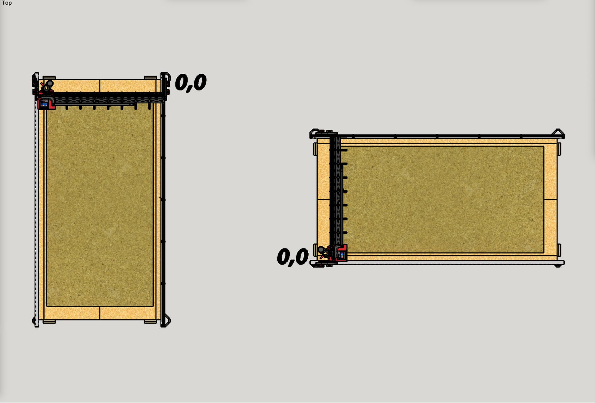
Switching where the machine homes to is not only something I’m aware of and would plan to do, it’s one of the most welcome parts of the change. Currently (and for the whole time I’ve had a LowRider), due to how my room is laid out, my control box is on the opposite side of where the machine homes. See table on left in illustration below. This means every time I home XY and get ready to find the Z height for the work piece, I have to manually jog a long way to keep from the router being out of reach while I am at my LCD. The table on the right shows how it would home after the switch, to the same side where my LCD is located.
You can easily make a macro to home the machine and then move to the other end of the table. The hiking position seems like it should be more important to the mechanics and the firmware than the user.
I would not dream of suggesting a new default, and I certainly understand that having picked one option as the default simplifies design, testing, and support. I’m just up against a particular room configuration and would prefer (and it really is just preference) to have it switched. I just need to think about whether my preference is worth the ramifications of redoing the setup.
My current thinking is to swap the XZ plates, print mirror reverse versions of the stubs and X endstop, and a new X endstop switch mount, designed to go on same side of core as the stepper motor, so that the gantry does not have to be turned 180, which keeps the Y end stops as they are, and keeps easy access to the router from the end of my table. *note: the above axis names are as is, before swapping X and Y.
A mirror imaged core is pretty much a necessity to reverse the X homing direction. you should not need to swap the XZ plates, but print the mirrored stubs and tensioner.