I am brand new to the world of mpcnc. I have started procuring my hardware a little at a time and I am just over 53 hours into printing the parts. Not in a rush to complete this, yes i am, but I also want to do my homework while i play the waiting game. The goal is to mainly use my machine for CNC wood, and maybe put my wife’s cricut maker to shame. My main question is about the spoilboard and the pros and cons of a slotted style vs a perforated top . TIA
I built my MPCNC with a perforated top rather than a slotted top. The reasons for this were:
- The costs of the rails for making a slotted top are extortionate here in the UK.
- I would have to either make a series of channel in the board OR built it up around the channels. I had no confidence in my abilities to do it properly.
- Using holes and T-Nuts was easy and cheap.
I can buy these
for £9.
I needed to do four operations for each hole:
-
A small pilot hole (2mm) from the front to the back at 50mm square intervals across the whole board. I used the CNC machine to do the holes in the cutting area and then extended the holes to the non cutting area by use of a large ruler. Having the CNC doing the initial holes means that the rows are parallel to the X axis which is important for me.
-
I turned the spoil board over and I then drilled a 25mm hole, using the pilot hole created, approx 2mm deep on the back to accommodate the backing plate of the T-Nut.
-
I then turned the spoil board back over again and drilled a 8mm hole from the front to the back to let the T-Nut slot in.
-
I then countersunk the front hole with a countersink drill that appears to be made from chocolate.
Given I had circa 200 nuts to do, that’s a lot of drilling, over 800 operations and at the end of it I hated the board, BUT it works well.
Rob
1 Like
I was planning on doing the exact same thing. What thickness spoil board did you use? My only concern would be the T-nuts potentially getting snagged by the router bit should the depth of cut go too low on the Z axis. How many mm do you have to spare?
I used 3/4" MDF for my spoilboard.
I used threaded inserts that are ~1/5". I used the CNC to cut the holes for the inserts and then screwed the inserts into the board so that they sit inset to the top of the board.
This gives me about 1/4" of clearance if I overcut my part.
Using the threaded inserts kept me from having to take the spoilboard off the machine to install the t-nuts from the bottom.
You can read more about mine here:
I used 18mm MDF as thats all the local wood shop had. I brought a 2.4m x 1.2m sheet.
The T-Nuts are a long way down and its not been an issue with collisions (at least not yet :)) They are 8mm high, so taking into account the 2–3mm for the inset, I have 7-8mm of space before the CNC bit hits.
I didn’t use threaded inserts though, they may be better and may not need as many drilling and finishing operations.
Rob
I did a lot of thinking, reading, and watching videos before I created my second spoil board, and having used it for four months, I now have a list of things I will do differently for my third spoil board.
I went with inserts. A small part of the decision with cost, but more it was about the complexity of the build. With just a construction site table saw and construction grade tools, I could visualize places where things could go wrong. If you are considering slots, in addition to the aluminum ones, I did see a couple of spoil boards that milled the t-slots into the MDF. The results appeared nice, but it was a more complex process than inserts.
I used 3/4 inch MDF and these inserts from Amazon. Note for soft wood, I found three insert solutions: t-nuts like Rob used, my inserts from Amazon, and inserts designed to be screwed in from the “top” (i.e. they don’t have a flange). I read complaints concerning the last kind of insert where the insert would be pulled out by the force of screwing a clamp down to the spoil board. I cut the holes for the inserts using the MPCNC. I bored a hole for the insert then pocketed out a place for the flange. Once done, I installed the inserts then flipped and mounted the spoil board.
I went with 65mm rectangular grid for my inserts. I did this because It produced an 11 x 9 grid (99 inserts) and the inserts came in a bag of 100. Now using the spoil board, this distance is too far. I will go with 50mm or below when I have to change out the spoil board. Note I did see a few spoil boards with non-rectangular grid patterns where each was line offset by half from the previous line. I’m not sure if this pattern provides any benefits. Also I will put the inserts closer to the edges (especially in the front and left) than I did this time. The maximum size material you can clamp using the inserts is defined by how far apart the outer rows/columns of inserts are. Plus the front inserts define how far you have to lean over the machine to to install the back clamps.
I elected to mount my MPCNC on a base board and have the spoil board sit on top of the base board. When you surface a spoil board in the common configuration, you get a “pit” in the middle of the spoil board. This makes working on any piece bigger than your machine more difficult. In addition, I wanted swappable spoil boards (one short one tall), and having this configuration makes it much easier to slide spoil boards in and out. The price I paid for this configuration is a taller legs (18mm). So far I’ve haven’t noticed any problems introduced by taller legs, but if I do, there are corner brackets to help stabilize the legs. Note as part of this configuration, I moved my cable chain to the back of the machine. This is a longer run for the X1 stepper cable (across the machine and then back to the electronics in front), but now I don’t have a cable in the front that I have to deal with.
I made my spoil board a bit smaller than the working area of my machine (abut 1/2 inch on each side). I have a list of reasons including the ability to mill the front and left edge so that they are aligned to the CNC, ability to reach any point on the spoil board with different tools, some additional space for a vacuum hose, and the ability to cut t-slots in the board even after it has been mounted. So far none of the reasons I made it smaller have materialized. On the other hand, I have yet to have a project where I wished for the space back.
I’ve added some additions to by spoil board. I have a horizontal edge, a vertical edge and an L “bracket” that are aligned to the spoil board using wooden pegs and then screwed down using the inserts. I made these edges from 3/4 inch MDF and the edges are milled by the CNC so that I know they are aligned with the machine. There are some problems with this solution. First since I made these rules so high, They cannot be used if the milling leaves the work piece. For example they cannot be in a surfacing operation where the resulting stock is 3/4 or less in height, or if I doing a contour cut and the stock left is smaller than my bit width. Plus, since I used the inserts to hold the rules down, I have no near inserts to use for clamps. For my next incarnation of a spoil board, I will make my rules thin (around 5mm), and I will add some inserts just for these rules between the other inserts so that I can clamp over the top of the rules.
1 Like
I encourage anyone to avoid overthinking the spoil board, unless you want to really geek out on it.
If you are interested in being creative, you do have a CNC to lay out the holes. So there’s no reason for them to be in a grid. You probably don’t need the same resolution of holes far away as nearby. Here are some ideas for insert patterns:
- one dense row in X, one dense row in Y. Then dense rows at 45deg, 22.5deg and 67.5deg.
- The 22.5 and 67.5 can skip the first few inches of holes, since small parts can use the 45deg holes just fine.
- You can add even more holes out where those angles don’t quite fit, at 11.25 degrees, etc, but start even farther from 0,0.
- If your holes are about 50mm apart, and you are using an L bracket, make mounting holes for the L bracket at 0,12.5,25,37.5mm. You can adjust to move that bracket by 12.5mm in X or Y and have the other end of the work at a better alignment to the grid.
Most worl pieces are rectangles, and you don’t have to clamp right at the corner, so you can spread out that 100 pack of inserts pretty far by choosing where they go. It is also a good intro CAD and CAM project. Just remember to flip things if you are cutting the underside of the board!
3 Likes
I did boring.
100mm grid pattern, 12 along Y, 8 along X, total 96 T nuts.
I will change it for next time.
Small pieces, I find the 100mm spacing to be a little sparse. Large pieces, it’s a little dense. Sometimes, there’s nothing in the right place.
My spoilboard is separated into 4 pieces, each is 400mm by 600mm. I used the CNC to pocket the T nuts in 2mm for the 3/4" (I cleared 20mm) and then an 8mm barrel cut through. I used more primitive clamping to hold the spoilboard pieces down and let the CNC do the work. No, it did not need to be that precise, and as I stated, I’ll change it next time.
I’m using 5/8" MDF, as I have a 3/4" MDF base under that. I thought that 3/4" was a little overkill. My T nuts are 3/8" high, so there’s 1/4" of waste board that I can mill into without hitting the T nuts. I try to keep it to less than 1mm.
I made 4 different L brackets to move the 0,0 corner of the work in order to make clamping more convenient, but my most used piece is the part that aligns the 0,0 with the endstop homed position of the CNC.
I do note that there is some sag in my table. I just bought a surfacing bit, and I’m going to make a mini spoilboard that I will surface using the surfacing bit so that I know it’s exactly parallel to my mechanics. This way, I can move the home position to a known coordinate from endstop homing, and have a smaller surface that I can do precision depth work with.
As stated above, T slot is hideously expensive. I’d love to work it that way, but it’s prohibitive. If I ever hit it with an endmill, I"d cry. If I hit a T nut with an endmill, I’ll be sorry to lose the endmill.
I think I went through the same thinking process as you. One thing I didn’t say was that this is my 5th spoilboard as I cocked up a few. Things like:
- not recessing the bag of the board for the base of the T-Nut.
- Not using the CNC machine to drill the holes so that they are parallel to the X and Y axis.
- Cocking up the spacing as I thought Estlcam was working in cm when it was working in mm.
- Leaving one out in the rain by mistake.
I’m surprised I’ve only had to make five of them  The sixth spoil is going to be an elevated one that clamps down onto the main one. My CNC is for cutting foam so the legs and Z axis are higher than needed for ‘normal’ (whatever that means) usage. I will take the penalty of possible movement in whatever x axis but I have additional clamps already printed for the legs. Not sure about the Z axis yet, but lets see.
Your point on surfacing is also spot on. I decided not to surface the board as it is clamped to the main board with M10 bolts. I’ve checked both and they are flat enough for me. The pit in the middle, small though it might be, is still a bit and I decided it wasn’t something I needed or or wanted.
I love the idea of 65mm spacing to make it 99 holes, I just brought another bag of t-nuts.
No issues with pulling stuff through the hole.
Did the same with L-clamps as well, there’s a common theme here that we’re all coming to much the same conclusions (which is nice).
The two other things I did to help was
-
I brought these Heavy Duty Strap Flat 30 x 5 x 1000mm This isn’t quite the same bracket as mine has more holes.
-
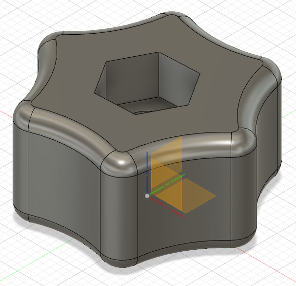
I made 60mm long mounting screws from 6mm threaded rod and printed knobs on the printer.
As some of my work is 50-60mm high and is foam, I can’t clamp down with on the piece of work, so I need to brace it with L clamps and a general clamp along the material.
Rob
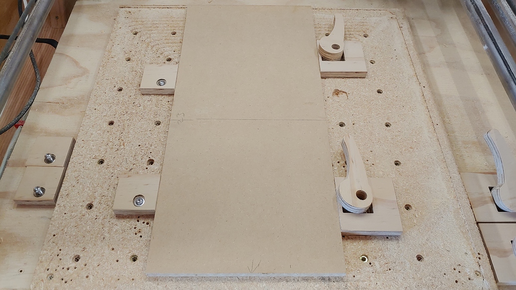
I got around the clamping issue by using adjustable cam-lock clamps:
The clamps on the right have 4 different lengths from the cam-lock and the edge. The spacers on the left have 4 different sizes from the mounting hole to the edges. This gives a lot of options for finding the right combination to clamp just about everything.
It does limit the size of the material I can cut using the existing holes. The plan is to add a few chunks of wood around the outer edge outside the spoiler board area that I can use when trying to cut something the full size of the spoil board.
Our CNC machines only provide forces in the x-y axis when cutting, so there’s usually not a lot of need to hold anything ‘down’. We’re mostly just trying to keep things from moving left-right or front-back.
2 Likes
@niget2002 do you have any models for the cam clamps you are using, i like that idea and want to give it a try on the MPCNC i am building.
2 Likes
Yeah, not exactly. That looks like it is useful for reference angles. I was just trying to be able to clamp as many rectangles with the fewest inserts.
Yeah, it’s a design for fixturing table. Just thought it sounded like you’d appreciate it
1 Like
There’s a link in my build page to the Fusion360 shared file.
1 Like