Downloded the latest Marlin 2.1.1, went through configuration, compiled, flashed - same problem. The day is pretty much wasted  Ordering new card.
Also try just M119 a bunch of times when not triggered. Wiring to the endstops could be intermittent.
2 Likes
@jamiek I did about a few thousand times. But it is possible that your comment fixed my problem Not sure yet.
Thing is: I can’t execute M119 command while the motors are homing or doing any other movements. If I send M119 while it is homing, I will only get the response after it has homed and the steppers are idle(r). The holding power is set to 80% of moving power in the firmware. So basically whenever I send M119, the motors are not working at their max.
So… if there is interference from the motor cables, M119 might not show it.
Next thing I noticed is that the endstop LED indicators may not always correspond to the values that Marlin sees. The LEDs are ON even when I reset the board and Marlin has not even booted. Marlin also has noise canceling and pullup/pulldown features, which probably means that in some circumstances it may think the endstop is open even though the corresponding LED might be happily shining.
Regarding the cables, I used a slightly thicker cable for the endstops, because that’s what I found in the local store and “thicker is better” anyway. Now I’m also thinking thicker might also be better for catching interference  And the endstop cables are all packed together with the motor cables in nice black sleeves.
With the suspicion that the motor cables can actually interfere with the endstop cables, I lowered the Y/Z power from 900 to 500 and did about 50 auto home cycles without any issues since then.
Yet another update
Lowering the motor power certainly helped! Then I decided to up the power again and see if I get the same problems again. Homing started to fail, but not immediately, after several minutes.
Then I lowered the power again, and the problem went away, but also after several minutes.
So at the moment homing works better when the board is cold and it also works better with the motor current down.
I need a beer.
When the motors are enabled, there is the max current flowing through them. As it sits there, the power is turned on and off with pwm. When they move, the direction of the current changes. The direction changes every 0.16mm.
It doesn’t work that way. The interference will have less resistance, but so will the signal. The signal to noise ratio is what matters. And it should be very strong, when the endstops are wired normally closed.
EMI is complicated. But the major component is that the area of a loop and the change in electric field cause a current to flow through the loop. If the area is larger, or the changing field is larger, you get more emi current. The electric field is changing quite a bit, because the motors are sending a lot of current and it is turning on and off. The loop is the area between the stepper wires. That is why cat 5 had twisted pairs. Each twist changes the direction of the loop, so they mostly cancel each other out, which lets many pairs transmit in the same sleeve. Replacing the wires with twisted pairs would reduce the emi, but shrinking them would reduce the signal as well as the noise. Unless I missed something. EMI is complicated. Since there are normally closed endstops, there should always be a current flowing through the wire. The current hours from 5V to the signal, through the endstop, and back down the ground cable. There should be about 1mA all the time, which should be much higher than the emi current.
You can reduce the noise through force. You have a loop to ground that is sometimes open. You can wire in a capacitor between signal and ground. When the switch opens or closes, the response will be slightly delayed (proportional to the size of the capacitor). That will make short most blips go away, but make the accuracy a small amount lower.
The thing that makes this hard to believe is that a lot of the firmware from MarlinBuilder releases has been used by hundreds of users and we have had thousands on previous versions. There is a first time for everything, but we haven’t changed anything in months.
I have spent a lot of time looking at logs, only to find out that the logs change the timing. I worry the logs are a red herring. But there is a first time for everything.
You said you are changing speeds. What else is different from stock? Have you done an M502 to restore all the settings?
There is a first time for everything. But in an effort to fix your problem: Why are you the only one having this particular issue? What about your software or hardware makes it different?
Maybe not the only one? Is this the same issue?
I had a thought…
Intermittent issues with the endstops is a weird one, should never happen. The software doesn’t care if the board is warm or cold, and the actual temperaturs doesn’t really change much from a “cold boot”
What might happen though is a voltage dip. If the voltage on the stop line doesn’t rise enough when the circuit is opened, it could do somethingmlike that.
A couple thongs to check:
-
Put a multimeter on the 5V line. If it dips at all, then it coupd be a bad or.weak regulator. Those could be supplemented with an external 5V PSU. You are looling for a dip in the voltage when the motors are operating.
-
Also check the signal line voltage. A mumtimeter should not draw enough to change the voltage any, but check that it is very near 0V when the switch is closed (not stopped) and higher than 2.5V when the circuit is open (at endstop) this is the voltage that you get with the pullup resistor “feeding” the signal line while being drained by the LED indicator.
-
If the 5V rail is not sagging, try an extra pullup resistor. Iirc the pullup resistor onboard is 470k. 5V going through 470k isn’t a lot of current, about 1mA or so. The signal line can handle literally 100 times that much. Another 470k between the 5V pin and signal pin would double that, and using something like a 220k would be safe and definitely signal a logic high. This could.elimimate noise issues. It could also make the difference if the logic pin is sagging because of the LEDs.
-
Noise could be a problem, too. Crosstalk from the motor drivers could be confusing the logic board. The higher current draw from additional pullup resistors should drown out any noise keeping the open circuit from triggering.
-
More extreme, but power efficient and noise proof is to wire your stops with 3 wires. On the switch, there is NO, NC, AND C. (Normally Open, Normally Closed, and Common.) (+) goes to normally open, (-) goes to normally closed, and (s) goes to common. No resistor should be needed, but a 220k resistor could go on the positive pin for short circuit safety. This will give a direct connection to 5V when the switch is triggered for a very definite logic high. If the firmware doesn’t pick that up, something in the hardware is toasted.
I think my problem is same as Karolis’s.
Below are links to videos of my problem. You will hear a loud noise, so turn the volume down to play. 
I’m waiting for a new motherboard to change the motherboard and test it out.
@vanillasky9, seems very similar, yes. Not sure if that’s related, but I noticed we are using the exact same stepper motors from stepperonline.
The only difference form my setup and the rest of the machines here is that I am using a taller YZ plates. Everything else seems to be almost identical. Yesterday I was testing all day with the default firmware and default settings.
One other thing I need to mention is that the problem only occurs with dual endstops and the first endstop ALWAYS works. No matter if it’s Z1 or Z2, whatever gets hit first will work fine. It is the 2nd one that fails.
From the information on this and other threads in the forums, I got an impression that this is an issue with the board, which I can try to investigate and possibly fix myself. I am not sure I want to go this way ATM. I’ve spent so much time and effort on this that getting a new board just seems easier. If another board works, I will know this was a board problem and try to return the old one as defect. If not, I will go through all @SupraGuy suggestions.
Thanks again for all the comments and help.
Are you sure your endstops aren’t swapped?
1 Like
Sorry. I got confused about who is the OP on this thread.
1 Like
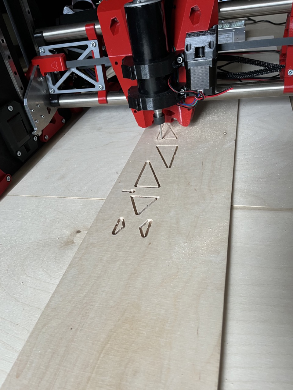
So I did my first cut, and (surprise!) it wasn’t deep enough, as I used the wrong offset in Fusion 360 2D contour. But since I have homing on my machine which (kind of) works (with lower motor power, stealth mode enabled and lots of prayers), I thought there is no need to worry. I fixed my gcode, homed the machine again, moved to the same coordinates and started a new cut on top of the previous one. And (another surprise!) the new cut was off by around 1mm on the Y axis. Not pretty!
This made me wonder how accurate those cheap mechanical endstops are. Is 1mm difference from the previous cut normal? Would optical endstops be more accurate?
Absolutely not. They should be more than accurate enough for our uses.
Kind of? Why stealth mode?
Because reducing motor power and stealth mode (probably reduces power even more) help with the endstop issues I’m having. Apparently when it does home, it still doesn’t do it very accurately.
Probably the best thing to do while I’m waiting for the new board is either not use homing or restore motor settings to defaults after homing.
I highly suggest you stick with ALL the firmware settings as we have them while doing any testing. Changing firmware introduces thousands of variables that make it too difficult to help.
Try just physically separating your end stop wires from all the rest by more distance to see how much that helps.
So … a few weeks later I received yet another SKR Pro board…
.
.
.
and…
.
.
.
.
.
.
.
.
.
.
.
… wait for it …
.
.
.
.
.
.
.
.
.
Problem solved! I homed it 20-30 times without issues with the machine cold and warm and with increased and decreased motor power etc… no issues at all ! (so far). Will do more testing tomorrow.
Regarding motors getting hot at 900ma… mine were completely cold. I think I noticed a few skipped steps during some cuts, so I increased the current using small increments and left it at 1200ma. Anything higher than that makes the stepper heatsinks hottish while the motors are only slightly warm.
Next tasks: make the table more rigid, connect the vacuum and finally do the first foam cuts! I am slighly worried that the super light foam chips might clog the vacuum quickly, but we will see.
1 Like
Fuck my life, the problem is still not solved
It still seems to depend on the temperature, worked fine yesterday when I tested the board in a box without the lid. Today I put the lid on, after some 10 minutes everything went back to weird mode.
I will be replacing the endstop cables and go through the list of suggestions from @SupraGuy . One thing I noticed about the endstop cables is… not sure how to say it in English… basically the cables are thick, but there are many wires inside that are super thin and when I solder them they have a tendency to burn and get damaged. I think the contacts might be weak.
TMC drivers will reduce their current if they get too warm. You may be setting the max current to 900 or 1200mA, and it is dropping it to the point the motors are cool to the touch.
The fact that it works without a lid is a good sign that the drivers need some cooling. Instead of a lid, install a fan.
The serial log can give you a hint about this. IIRC, there is a print anytime the current setting changes due to heat. M122 also has a lot of info, including OT prewarn (which is over temp pre warning).
3 Likes
Inspired by the example from @vanillasky9 , I soldered a few resistors on the back side of the SKR Pro:
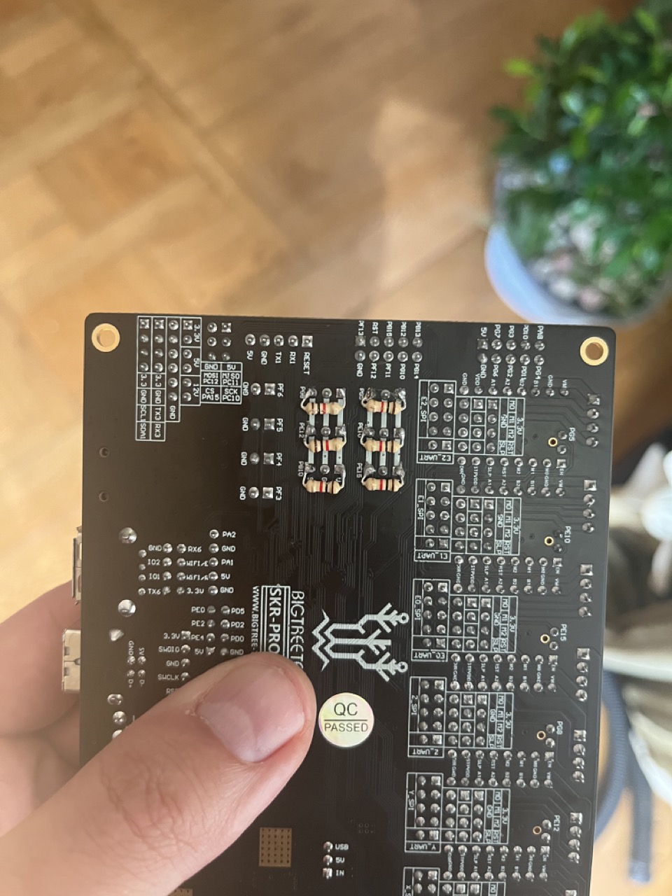
In the end this seems like a very simple solution which doesn’t need any cable rewiring etc. So far homing seems to work, will see how it goes in the next few days after I do some cuts.
Overall the 2nd board worked better than the first one. I did have homing issues but not nearly as often as before. Also, the first board usually failed at homing Z axis, and the 2nd board usually failed at X… Hopefully this solution takes care of both problems.