So does anyone run items from teachingtech on their mpcnc? I was wondering if the firmware would respond the same for calibrating x y z?
In what way?
I never really checked if 10 mm is 10 mm is all
Well you can draw a square and measure it, but more importantly is cut one in your desired material and adjust acordingly.
I will say your machine has a fixed gear ratio and should be very very close.
1 Like
If you’re thinking of the Teaching Tech 3D Printer Calibration site, a lot of gcode automatically generated on that site is printing-specific. Things like extrusion multipliers, first layer height, retraction, temp towers, tuning acceleration to remove ringing, etc. just don’t apply to a CNC router like the MPCNC Primo or LowRider (unless you’ve got a plastic extruder attached).
Mounting a pen and drawing some shapes will allow you to test steps per mm and verify your machine is square in X and Y. Checking Z perpendicularity can be done with something as simple as a bent wire from a coat hanger.
Setting up a touch-plate of known thickness (like the Tiny Touchplate in the V1 store) will get you reliable and repeatable tool height settings.
“Speeds and feeds” are going to vary depending on combined characteristics of the machine itself, the tool (both spindle and bit/cutter), the material, and the job. You’ll need to experiment to get optimal performance, but there’s good “getting started” info on the Milling Basics page here on the V1 site.
2 Likes
Sorry I wasted your time in asking this. I just did a simple circle part in Tinkercad and put in a straight tool and went to town. 50 mm outside measures 49.73 10 mm dowel type center is 9.73 and 10 mm depth is 9.79
from plastic and conduit, wow!!! Now to figure out what I am going to do with it. I am not the most creative person in the world, but give me ideas and I can usually work them out.
1 Like
Make sure you do a full depth finishing pass, I bet those numbers will tighten up a bit.
So here is a pic of a piece of 1/4 ply i put into my test cut. I also changed to a straight router bit. You can see a very slight gap, is that due to my machine or tinkercad or is that Good??
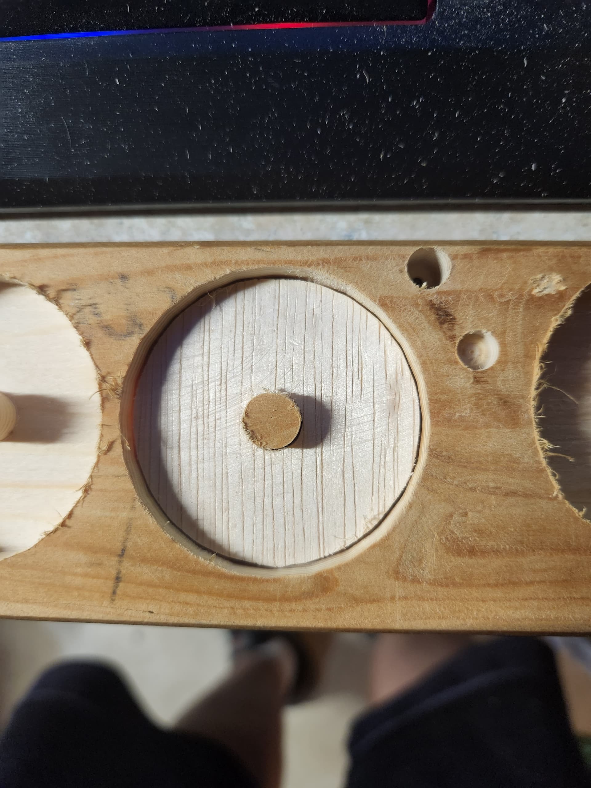
actually, I think it is tinkercad. I see the round has 24 sides, so it maybe creating that gap.
If you can increase the number of sides to something a bit higher, like 64, you probably won’t be able to notice them on the final result (number needed somewhat depends on the size of what you’re cutting, I suppose).
1 Like
Never a waste of time to ask an honest question.
I hope my answer didn’t come across as thinking you didn’t have a valid concern.
1 Like
No worries, no problems/issues here at all.
1 Like