The S-curve is a good thought. That would imply a limit on rate of change of acceleration I think? (I.e. actual jerk, not Marlin “jerk”.) I can turn that off and also switch to Marlin jerk mode and play with different values. Jerk of 0 should obey the acceleration limits and higher values would instantaneously jump from nonzeo positive to negative velocity, and I should be able to produce skipped steps by just cranking that number higher and higher until something happens.
Now we’re getting somewhere. This is with jerk (no junction deviation) and without S-curves, and first try with super high accelerations I got missed steps, where previously it wouldn’t.
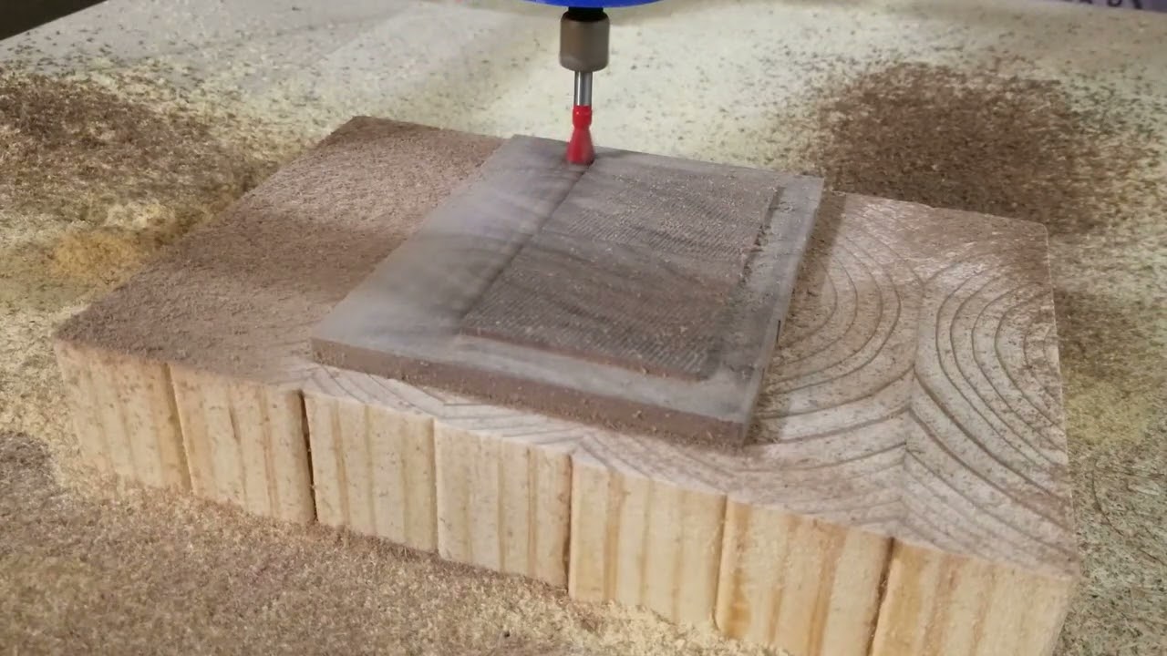
I had made an option for surfacing, which makes cutting strokes in one direction only. This was based on the idea that a not-quite-trammed cutting bit could have a low side and a high side, and the low side should be leading and the high side should be trailing in order to avoid burning.
I found myself using it for cutting boards too, but it had terrible tear-out on the last pass where the tool cuts away from the workpiece. I also had to “cheat” with a slightly larger size so that the plunging movements were outside the cutting board area. The dovetail bit I’m using is not able to plunge at all.
I added a ‘perimeter’ option for this situation and now I can tell it the actual size and just go:
I thought this might be helpful for other folks too, to skip the CAM for such simple jobs.
This is great! @jamiek
I’ve been fudging with making Inkscape rectangles and Estlcam pockets.
Estlcam forces a perimeter at the end, which I don’t usually want, and has the cutting in both directions issue like you mention. So this solves both those issues.
A thought…I just ran your generator and noticed the rapids are G1 instead of G0. It’s easy for me to replace myself afterward but wondered if there was a reason you had left them as G1.
No reason for G1, I just didn’t think of it because for me it doesn’t matter.
Simple enough for me to replace them in the generator, like 2 minutes.
…Done.
Perfect!
I usually throw the code in a visualizer first. G1s show up white and G0s red so it’s an easy check for where the actual cuts are.
Thanks
That’s a great point. And a GCode Visualizer for Octoprint could take advantage of something like that too, hypothetically speaking. I hadn’t thought about it, but I gather that CAM tools generally retain the distinction between G0 and G1, in which case that’s the best possible way to decide how to render the segments. Win!
If you’re thinking more about it then the move to Z clearance is probably also a rapid.
So if Z clearance is 0.5 then
G1 Z0.5 F800
G1 X0 Y100.000 F2000
G1 Z-0.5 F800
Would be
G0 Z0.5 F800
G0 X0 Y100.000 F2000
G1 Z-0.5 F800
This is nitpicky though 
I’ll take it!
Updated.
@jamiek
I’ve been using the generator for a couple of surfacing jobs and it’s great! Thanks again.
By default you have 0,0 on the bottom left, which is where default should be of course!
How hard would it be to allow someone to choose 0,0 to be bottom right? Or centre? Some standard locations like that.
I’ve been using the bottom right side of my spoilboard as my starting point because my workbench is on that side so I always use bottom right as 0,0 on my Estlcam jobs. Or centre if the carve calls for it.
Just wondering if it’s a quick change or not.
Cheers!
Are you using the G92 X0 Y0 Z0 option?
I’m thinking it will be a substantial change to generate offset coordinates, but adding an offset to the G92 line could be pretty straightforward.
Here is an unrelated situation that could benefit from a similar feature:
Suppose I’m flattening a cutting board and visually I have a pretty good guess at where the low spot is. I can start only in the lower left corner and I don’t know how far down I need to cut to make sure to clear the low spot.
What if I place the bit on the surface at the low spot, and measure the X and Y position of the bit relative to the edge of the workpiece. Then I enter those values into the generator so it doesn’t generate G92 X0 Y0 Z0 but instead inserts some nonzero numbers as G92 X### Y### Z0. Then when the job is run, it cuts to the specified depth relative to the low spot.
It’s straightforward enough to edit the gcode file manually, but one of the ways I’ve started using the tool is to download to my phone and uploading to Marlin from my phone, so editing the gcode is not convenient unless I go to the other room.
Perhaps this can also work for starting points other than the lower left corner. The coordinates in the gcode would not be any different, but by specifying a starting point at the center or a different corner, it would have the same effect.
I set G92 X0 Y0 Z0 manually outside the code.
Hmmmm…
Following through on your idea, I moved to the bottom left point from my parked position on the bottom right. Not that complicated since it’s moving in the negative x direction the width of the carve. Then I set X0Y0. Then I moved to the high point on the board and set z=0.
But my first step should have been something like G92 X200 Y0 if my board is 200mm wide. Then I don’t need to move to the X0Y0. I still have to jog to the high point to set Z.
That’s just a bit of workflow logic I was not thinking through.
Edit: I use bench dogs to square up pieces in the bottom right corner so that’s why I know where that location is
I have also done something similar, where I disable G92 X0 Y0 Z0 in the gcode generator, and I manually set G92 X0 Y0 at the lower left and G92 Z0 at the low spot, and then run.
It sounds like if you are already doing the G92 manually, then you have what you need. My other concern is for someone using it for the first time, it’s easy to get it wrong and crash the machine, by entering the wrong polarity for example. It’s safer to make the g-code generator slightly dumber and much easier to correctly predict.
I think most setups probably have people squaring off the bottom left in any case.
Your explanation made me realize what I was missing, so all good!
I went through a mental rejig when I started using machine coordinates as part of my setup workflow and then again just this week when I got my z-probe up and running. This one should be easier to ingrain 

