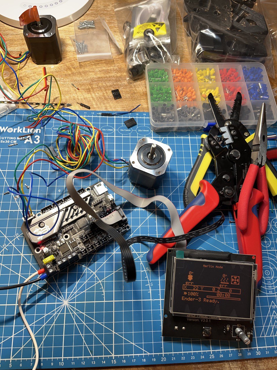
I wired the electronic components to make sure everything works fine. I connected my controller board (running marlin) to one of the steppers. Then I go the marlin interface (I have a display connected to the controller board) and select a X movement. As I move the potentiometer knob I can see the stepper turning but not in the way I’d expect.
Thank you for the reply Paolo. The document didn’t help me that much though.
I did some research and I think my connections are correct.
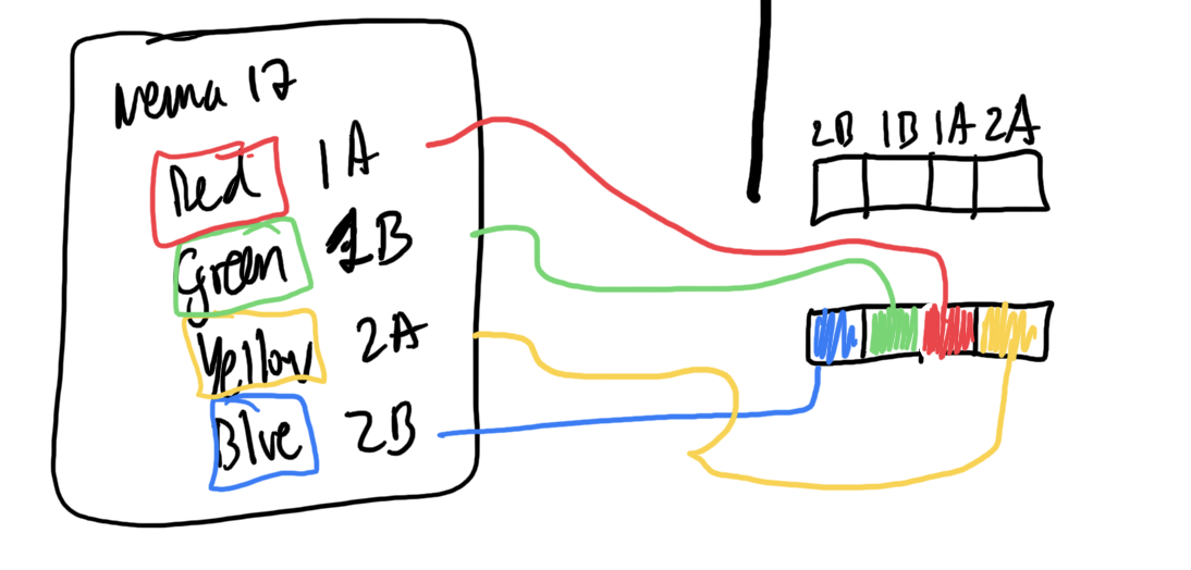
First, I measure the resistance on each of the 4 pins to find the coils. I get resistance (~3 ohms) on pins blue and yellow (that’s one coil). The other two pins also have resistance so coil two should green/red.
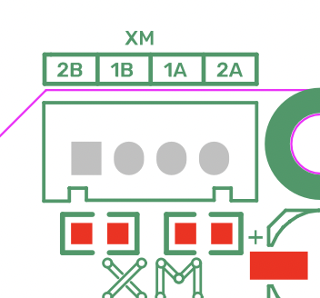
Then I look at the control board pinout for the x axis stepper port and I see:
So I connect blue/yellow to 2A/2B and green/red to 1B/1A.
I guess I can try to shuffle the cables and try all the combinations always grouping together cables from the same coil.
I’ll try that and report back. Let me know if anyone else has more suggestions.
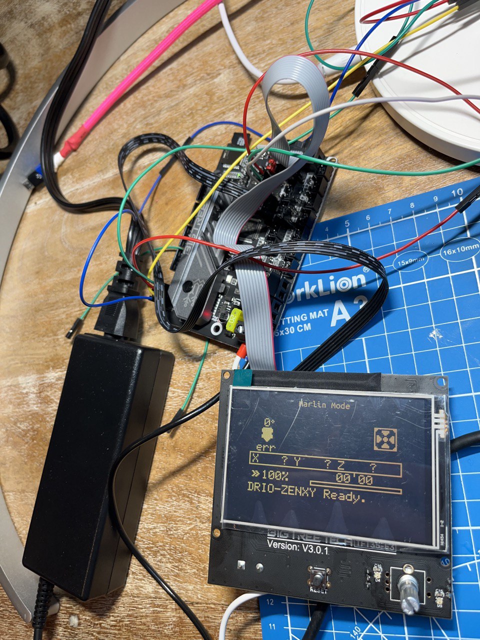
This is my controller/main board running Marlin. The board is running marlin although not the latest firmware.
I have tried to change the Drivers current from 0.6A to 1, 1.2 and 1.5A without success. Same results. I think 1.5 is the current the stepper require? Is there anything I can change from Marlin?
I connect the SKR board (XM socket) to the stepper as follows: red cable (1a) from stepper motor to pin 1a in the SKR, green cable (1b) from stepper to 1b in the SKR socket, etc… Is there any other way to I can try to connect these?
Some questions:
Are the signals/pulses between the stepper controller and the stepper motor standard? How does the SKR and firmware know what signals to send to make the motor move correctly?
Would updating the SKR firmware to the latest version help here?
Yes bipolar stepper motors are a pretty standard afair in the sense that I believe you ask. All bipolar stepper drivers will have the same DC PWM output to the coils, each pole opposite phase, etc. Settings for the SKR that can affect the signal to the motor would be a) current, and b) microstep configs. Sounds like you already got around to playing with current, and 0.6A is already plenty to get a piece of red tape turning in the air. Microstepping could cause this even without a load, if it is trying to move very fast and the microstepping is set too high.
Meh, doubt it. The e3 board has been out for some time. The only changes you are likely to get by upgrading to later marlin versions won’t matter at all for a zenxy. Unless your board came loaded with some obscure configs (should not be from factory), then I am pretty sure it has reasonable values for acceleration and speed.
From the video, it appears the MCU is sending the pulses it should to your drivers. Since you already tried massive current out, I’m guessing it may just be a wiring issue. Just try swapping the stepper wires around and see if it works. You won’t damage anything trying. If that doesn’t work, I’d probably double check configs and recompile fw to make sure it doesn’t have some insanely high acceleration and velocity limits.
FWIW, I have a zenxy working great with an skr e3 v2, with TFT.
[edit: This page, in the ‘Methods and procedures’ section, there is a chart for the ‘Trial-and-error method’ to determine wiring.
Using that, you can sort out wiring with just 3 different configurations. In other words, your wiring now would be “arbitrary”… trying the other 2 sets of connections should get it working, if it is just miswired. Note once it’s running, it may be backwards. If so, as the page advises, just switch either the ab pair or the cd pair to reverse direction.
Yes, using a multimeter to measure coil resistance also works, but this procedure can work around potential issues with testing coil resistance.]
Thank you, Kev. It worked! I did not have the cables properly connected. I started trying different combinations until it worked. Now it moves smoothly at 0.6A / 12v.
This is how I ended up connecting:
SKR: (2b, 1b, 1a, 2a)
Stepper: ( blue-2B, yellow-2A, red-1a, green-1b )
Since you use the same board, let me ask you:
Are you using the neopixels? The connections are pretty straight forward: ground, data, 5v. I have tried an old strip I had and run the BigTree firmware (not marlin) and when I enable the neopixels (via the UI/display) the strip does not turn on. It is possible that my strip is dead but I wanted to ask if you have tried the neopixels with your boards and if you have to do anything other than connect the strip to the board.
Can you control the neopixels when running marlin instead of the bigtreetech firmware?
I use neopixels on my printer, which uses a btt GTR v1.0 and marlin 2.1.1. Works great, but it does require configuring marlin with the pin#, number of neopixels, type (RGBW, GRB, etc), etc. The fact that you can access the neopixel menu means you do have it enabled in firmware, but it is likely not configured for the correct number and type of neopixels. Due to how specific the marlin neopixel config is, I highly doubt you’ll get them working without recompiling firmware. If you’re willing to do that, myself and others can definitely help you get there. We can use my working skr e3 zenxy configs for the most part… just tweak it to fit your newer board and your neopixel layout.
Edit: side note… BTT firmware is marlinfw… just a precompiled version with BTT’s combo of configs. AFAIK, there’s no way to change the neopixel config outside of recompiling, so you’ll be doing the full monty if you want neopixels on that. Learning the basics of configuring marlinfw is extremely valuable to anyone doing cnc or 2d printing anyways; you can learn now or later, but I guarantee you’ll have to learn it at some point if you stick to the hobby.
I have my building pipeline in place. The marlin documentation is pretty good and the process is straight forward.
To test the pipeline I built marlin 2.1.1 for a generic board (mega2560). All good. I am ready for the config files.
A few questions:
I see BigTreeTech has a fork of the marlin code base for the SKR. Should I work off of that repo or should I use the original marlin one?
Is there any way to save the firmware I have running in my SKR?
I am currently using the TFT35 E3 V3.0.1 display to interact with my board. Eventually I want to plug a raspberry pi so I have more flexibility but for now it is probably better to use the display. Just curious, if you use a pi to control the board (3a) I guess you have to connect the pi to the SKR via the TFT connectors. (3b) What do you run in the raspberry pi to control the board? (3c) Do you have access to the same functionality as when controlling the board from the display?
There is a zenxy skr pro 2209 firmware at MarlinBuilder releases. I would start there. There may be newer versions, but I doubt any changes will help you with a zenxy table.
No. Unless there is a firmware.cur on the microsd card in it.
It connects via USB.
Octopi is probably the safest choice. V1pi doesn’t have any sand table specific features. Sandypi is another option, which would be great, but has less documentation/history.
The best reason to use a pi is to just ship the gcode over wifi and then control it from your phone or something. You can do everything with the screen though.
Thank you, Jeff.
Octoprint sounds like a great idea, specially considering I am going to have to send different firmwares until I get the right one.
I will start working on it. I think Kev was right:
Learning the basics of configuring marlinfw is extremely valuable to anyone doing cnc or 2d printing anyways; you can learn now or later, but I guarantee you’ll have to learn it at some point if you stick to the hobby.
Kev, if you have resources you want to share (config files), please send them my way.
If this is too confusing, or over the top, then feel free to ignore it.
We make a script that configures marlin for us. I don’t recommend doing it that way if you are just one person, using it for themselves.
But this script does show you which settings we change for a ZenXY build. It will help you know what to look for. Not all of them are strictly necessary:
For example, we enable CORE_XY and set EXTRUDERS to “0”.
All these changes, and a few specific to the skr pro are in the marlin firmware I posted. It would be a good reference for you to work towards too.
It is just that these seem config options I should change once I have a basic working firmware that I can build myself.
My intention as a first milestone is to build a custom firmware that lets me do what I am doing right now with the firmware that came with the board: controlling the steppers, show the menu/info in the display plus controlling the hardware from my laptop running octopi. Yes, very modest but I have to go in little steps. Then I will build on top of that.
Once I get that running it seems is just a matter to keep changing the config files to tune the hardware to the specifics of the project (famous last words).
I want to report that I have successfully built a custom marlin firmware (Marlin-2.1.x stable branch) for my board. I have not updated the board yet with this new firmware but this is an important milestone – I think. Notice there are still tons of options enabled that I can disable because I am not using the board for 3d printing.Those are the options in the config (shell script portion) options jeffeb3 sent me.
The environment is STM32G0B1RE_btt. You can set it as default in “platformio.ini”.
$ platformio run -e STM32G0B1RE_btt
...
$ ls -lachd ./.pio/build/STM32G0B1RE_btt/firmware.bin
-rwxr-xr-x  1 drio  staff   139K Sep  8 05:07 ./.pio/build/STM32G0B1RE_btt/firmware.bin
TODO:
Apply the changes that jeffeb3 sent me and recompile. The file you passed me is for the shell scripts that generate the configuration files. Makes more sense to change those values directly in configuration header files.
test the firmware on the board
BTW, no, you cannot update the firmware on the board directly from octopi you have to copy the firmware to the card.
disable REPRAP_DISCOUNT_FULL_GRAPHIC_SMART_CONTROLLER (not compatible with my platform/cpu) and use CR10_STOCKDISPLAY (which is compatible).
My questions are:
Can I leave extruders to 1 without affecting functionality?
What display should I use. Mine is the TFT35E3V3.0.1 but I don’t think it is supported. I am fine with using a generic one and use the knob instead of the touch screen. I am going to do more digging with this. The firmware from Treetech that came with the board worked fine so that means it has to work I just have to find the right config values and perhaps adding some extra code to support the display.
I have created a github repo for this so it is easier to track changes.
Yeah. Those errors are really telling you what else you need to fix. Start at the top and work your way down. It is probably things like having esteps per mm set, but not having any extruders.
You can set the thermistor to the dummy thermistor and it will just pretend to be that temperature. Then you can keep the extruder. We used to do that on all the builds. We switched to zero extruders because 1) it was available 2) it made sense 3) we wanted the driver to run X2 and Y2, which aren’t a problem on the zenxy.
So… If your screen has a “Marlin mode” by holding the knob down for 10s, then that is the REPRAP_DISCOUNT_FULL_GRAPHIC_SMART_CONTROLLER. It will work with your cpu. The error was probably something else, like missing u8glib or something. That is the most basic, most common kind of screen.
The “Tft mode” doesn’t need to have any specific marlin setting, except the serial port 2 needs to be enabled for whichever serial port you attach the screen. The tft mode uses a serial port to talk to marlin just like octoprint would.
There are a few more config options we set. This is the top level file. It calls a couple of lower level files, like the zenxy one I pasted. Many of these other options are for the skr pro or the tmc drivers. But now that you know what you’re doing. Take a look at those files too:
There may be something useful in them for you. If you have a question about why we set them, I can do my best to answer. If you paste an error message here, I can give you best advice too. Just beware that sometimes only the first one makes any sense.
An interesting thing that I found is that my display is very “smart”. It comes with its own CPU and works in two modes: marlin or BTT. In marlin mode, is the controller board sending pixels info to the display. In BTT mode, the display sends gcodes via the serial port (TFT). In my firmware, I work in marlin mode. I will be adding a raspberry pi to control the board via gcodes. That is basically what the display does when works in BTT mode.
I know this is well know for you all but I am sure someone maybe find this useful in the future.
Next task, getting all the V1E options that Jeff sent to compile. I will continue reporting.