That’s a great design. Simple and effective.
2 Likes
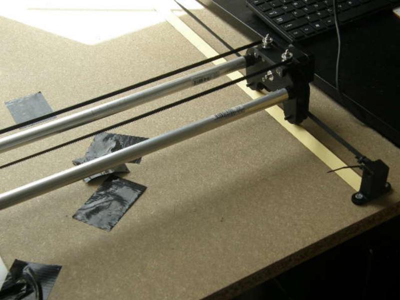
Well, I’ve built it, installed the electronics and wired up all the motors the right way around. I am using an SKR Pro with the standard serial wiring.
The first thing that I’ve run into is the lack of limit switches. I am used to automatic homing on 3D printers, so this is shocking to me. I will be changing to individually wired motors with end stops for every one. I have noticed that the motors are easily powerful enough to damage the machine so, in my view, homing and correctly limited x, x and z travel is a safety issue. I think that it impacts ease of use too.
I will try to use Klipper with Raspberry Pi too as I think that, ultimately, this will be a better system. I am looking at building a dinky Voron Zero as a fast 3D printer; that uses Klipper by default.
I had also under-estimated how much of a learning curve CAM is for a CNC mill. I am using Fusion 360; it is powerful and complex. I have spent several hours on YouTube already trying to learn how to use it.
I have no regrets about building the Lowrider: I am learning so much!
I’ve been happy with sensorless homing on my lowrider though they require the right controllers.
The endstops on my mpcnc burly have given me fits and I may switch it over too if I start using it more or convert it to a primo.
1 Like
@jchidley. That is a nice solution. I am currently printing the plates as when I originally built my lowrider I stupidly chose a cheap plywood…it is way too soft and it bends! . I have PLA to hand so why wouldn’t I give it a go!.. After that I might just go get some more steel pipe (like you I elected to use cold rolled steel pipe as it was what was available in my area), and have a go at your design of x axis. Any chance you could publish your bearing mounts please?
Hi Jack
I wired the end stops because I thought it was important to correctly resetting the 0,0,0 if I repeat some cuts on a jig. This is true but so far on one off parts I am resetting the origin on every cut anyway.
Where endstops are handy is squaring up the Y and Z but in practice you can just manually run the Y to the ends ( I added a screw to adjust and make it easy to square) and lower the Z on a couple equal blocks to square the Z.
On the safety issue, limiting XYZ travel - the end stops do not act as limit switches and if the Gcode commands it the axis will just drive over the endstop/limits. You have to be careful.
A workaround would be to wire another complete set of 6 switches just outside the endstops NC in series to a relay that would cut the power if the machine over traveled.
If I am wrong here I’d like to know so I can fix it but that’s how my LR works…
Yes, I will publish my designs when I am sure that they work properly and when I am sure that I can correctly licence them: I prefer public domain (e.g. CC0 and 0BSD satisfy people’s need for an actual licence). Obviously I need to be free of copyright conflicts or I will have to license them differently.
I have only printed the sides and router plate as a temporary measure. I will be cutting them out of good quality birch plywood on my CNC ASAP and replacing them. The 3D printed ones aren’t rigid enough for my taste.
Yes, I will have to be careful!
As for making sure that the router is correctly square to the table, I see that your manual method will work perfectly. However I am both lazy and forgetful so an automatic system is best for me.
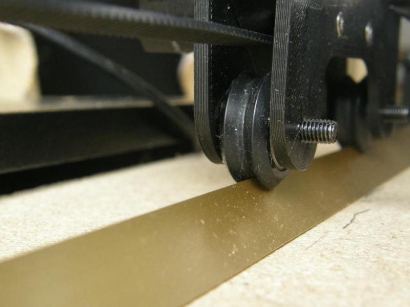
Be careful with the bearings travelling on the top of the rail as that is where the dust will collect and cause your z to bump over it. I have also noticed the fine dust likes to pack onto the bearings on my z tubes a lot more than on the original rubber wheels. You may or may not have that issues with your Y bearings
1 Like
I am sure that I will need something to scrape the dust off the rails. I think that I saw just the thing on Thingiverse
Ok… I have decided to use inverted right angle ali strip instead of round tube so will need to design my own adapter for bearings, thanks anyway. I use a similar setup for my foam ripper - although for that I use the Vslot wheels, the lighter loading allows me to get away with that solution. We will see if the right angle aluminium strip and two bearings at 45 degrees will be enough for the Lowrider…
We were discussing about such a solution before in this thread. I just wanted to build the stock LowRider2 before trying something advanced. I am curious about how your modification turned out.
Who is your remark aimed at ? If it was me then I haven’t started the mod yet, I am printing the Y plates at the moment as the plywood I used for the original plates is too soft and it bends under the weight of the gantry (12mm plywood …more like 1/16th balsa!)…
I am pretty sure the easiest solution is just to fit the angled aluminium rail against the side of the inline skate wheels but who wants to use the easy solution. 
It was aimed at you. Sorry - maybe my english is not so good. I just wanted to say that I am curious how your build will turn out. Especially when you go the inverted V route with the bearings. I think it could be a good solution because i imagine it is self centering and would avoid dust build up to some extent.
Its not your English, if you use either @ followed by a name like @ragadinks or use the reply button in the post you are referring to it is easier to follow the threads.
The Vslot wheels running on the inverted right angle rail works well on the foam ripper, but there is only light loading on the wheels, I’m pretty sure the sideways forces acting upon a Lowrider would be enough to dislodge Vslot wheels from the rails, I am thinking with having two bearings at 45 degrees to the vertical will provide at least as much resistance to sideways loadings as the skate wheels provide…I also think some form of support will be needed to prevent the rails from flexing sideways, it is only light gauge aluminium, this should be quite easy to achieve though with printed brackets, initially glued under the rails …time will tell.
Should particle build up on the rails be an issue that could be easily solved with some form of brush keeping it off the rail, I would have thought it is a common potential problem with the skate wheels, it is, to some extent, dependent upon the size of the chips you are making.
Just FYI (you may already know/plan on using), you can create a really nice v-bearing setup using a strip of the same Alu rail, flipped and tapped. The only reason for tapping the holes is because there’s not a lot of clearance inside the rail for nuts, and you can place the bearings across from each other in pairs rather than offsetting them. This was how I was going to run my X and Y axis rails before I found the MPCNC so many years ago…
1 Like
@kvcummins was thinking something like this -
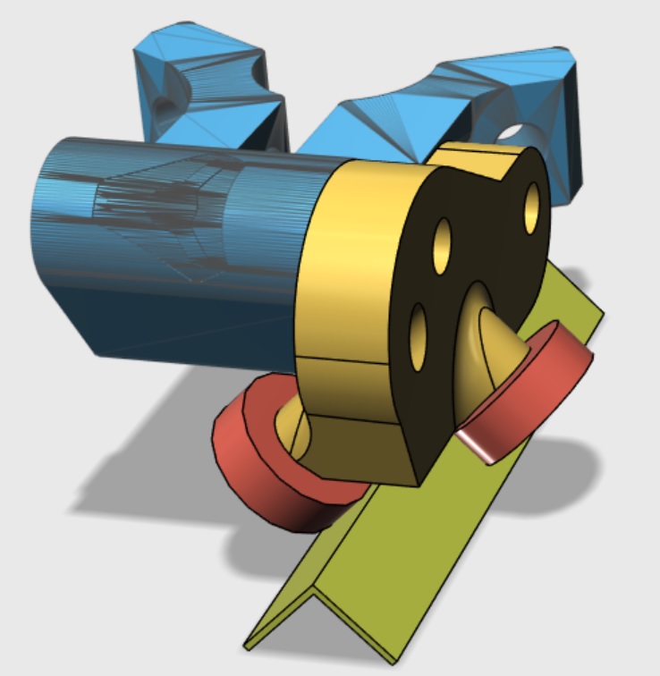
Thread the bearing bolts into the new bracket - saves the space for the nuts. 3 perimeters and 7.5mm diameter, I have a set of those combined drill and taps which are brilliant for creating an 8mm thread in this type of application.
I can’t quite visualise how you mean the rail flipped and tapped…??
Ain’t this technology wonderful for tinkerers!!
1 Like
Today I got Klipper 3D working on the SKR Pro 1.2 with dual end-stops for the Y axis and a single end-stop on the X. I designed both sets of end-stops from scratch. I’ll be adding a specific post sometime later.
I am holding off on the Z axis for the moment as, as far as I can tell, getting this wrong breaks the Z couplers. Also I haven’t completely decided how to arrange the Z end stops.
Once I have a working Z axis (with end-stops) I’ll be drawing the infamous crown.
Edit: Flexible couplers are cheap and available next day from Amazon (£6.99 for 5). So not a big deal if you break one.
I think klipper is my next 3D printer project. I want to try it on my gridbot. I haven’t tried it for the lowrider.
It’s alive!
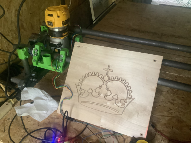
Only just, mind you. The belts and several bearings are loose, the wires are dangling everywhere, the bed isn’t flat and one of the z-steppers keeps losing steps. But I am happy: it’s running dual end-stops on X, Y; Mainsail / Klipper 3D and my old but never-before-used router. The work areas is as square as I can make it and it does the full range of travel. This is my very first CNC milling operation, ever, and the first time I have used Fusion 360for manufacturing and post processing.
All in all, I am amazed that it’s working at all!
9 Likes
I have been trying to surface my OSB using a 25mm 1/4” shank bit but I discovered a problem: the DeWalt 611 template doesn’t fit my DeWalt D26240K-GB version of the router. There’s about a 1mm difference in the diameter of the bolt circle.
As far as I am aware the 611 and D26240K-GB only differ in electronics / electrics but are mechanically identical. If the template is made out of wood then you probably can’t tell the difference but mine is 3D printed with recesses for the bolt heads.
This is a problem because the screws (M4 10mm) are only just long enough to fit but not perfectly so my router isn’t secured in the correct alignment: it is a few degrees off perfect alignment. I have bought 16mm M4 screws and made a shim to secure my router to the base - a set of washers would probably work just fine with the longer bolts.
Also, I ran into problems with my surfacing job. I wanted to fit standard width sheet goods (4ft or 1220mm) into my router bed but it turns out that you need extra space for the tool lead in and lead out on each side - at least 25mm I’d guess so my working area needs to be 1270mm at least for a 1220mm wide board.
Another problem is that Klipper 3D doesn’t natively support G2 or G3 commands because these are not necessary for 3D printing. 3D prints are based on STLs and these are just triangles and not curves. Thankfully Klipper has a workaround for this that needs some extra configuration settings.