To rail or not to rail

I’m seeing many LowRider topics where people are converting to rails. Some of the rail systems seem very reasonable, some… Well, if I wanted to spend that kind of money, I might not be looking for a LowRider, since there are several other DIY style CNC plans out there

I’ve never been entirely clear on what keeps the LR2 from skipping sideways. It seems to me that depending on the wheels’ traction is dicey when the surface might have some dust or chips on it. It seems that belt tension provides some stability as well, though I’m sure that I wouldn’t want to depend on that. The Z rails and Y plates should limit the amount of sideways hop possible, but I don’t see anything there they actually touch (or should be allowed to touch) the table.

I know that people have used C channel, or put angle on the table to keep the wheels straight, but that’s not far shy of just running a rail anyhow.

My impression is that the design as-is should be good enough, but as I said, I’m not really clear on what else there is to prevent sideways movement of the carriage.

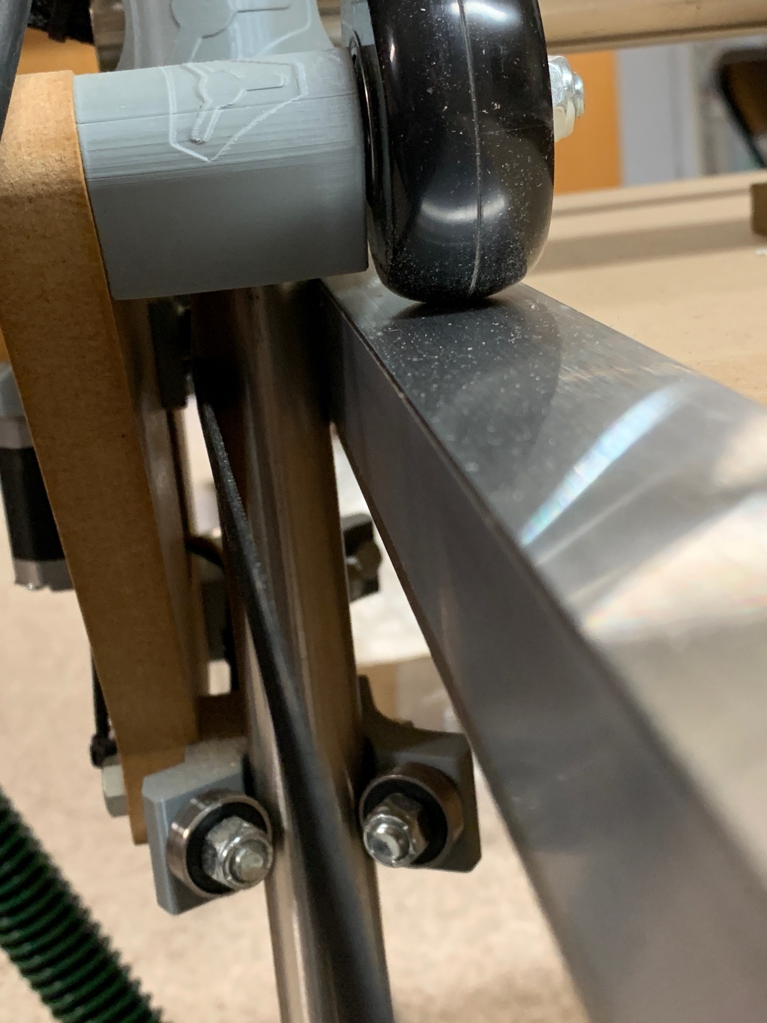
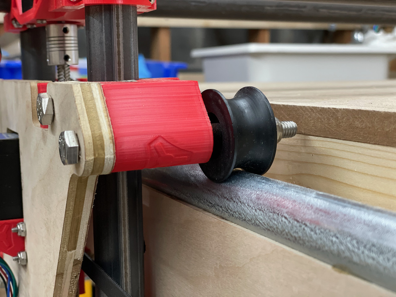
I quite like this solution using 1" tube. I might have to ask for STL files for those. I can get steel tube for relatively cheap. If I have to redevelop that myself, I might have both sets of bearings run at 45° so that I can drill mounting holes into the steel and run screws through it into the table edges.

I’ve been looking at getting a table started, and it seems that as a part of that, I might also be looking at setting up my MIG welder that’s been sitting in the garage for 3 years since I bought it. I got as far as installing the welding wire and gun, and haven’t welded a single thing with it. I have the cannister of argon gas still sealed. It’s just been easier to fire up the stick welder that I’ve got for the couple of projects that I’ve had, since the sticks also needed to be used up before they expired from absorbing moisture. Anyway, I thought that some square tube might be just what I need to get a table frame that’s nice and flat

I’ve never had mine slide sideways. If they slid then rollerbladers would be falling on their asses all the time.

2 Likes

Dan,

I’ve been only cutting on the lowrider for about a month so for what it’s worth…Most of the projects I’m running on it are for through cuts in 3/4 ply cutting at a 10mm doc.

What you are saying seems like it should be true, the damn skateboard wheels should lose traction and slide sideways when cutting hard but… it doesn’t… my x axis is fine. When the job returns to 0,0 it’s dead on.

I know some have issues with drift maybe they are doing longer jobs and there is an accumulation of error maybe it’s a squareness thing.

I’ve had to do a couple of job rehome and restarts on mine and the second cut has been clean over the already cut parts.

I used to watch roller bladers fall on their collective tails repeatedly next to the sandbox where my kids were playing.

People who are having difficulty are probably having build issues, but there have also been a lot of “convert to rails” threads lately, or Jeff putting that angle beside the wheels. Makes me paranoid.

Well, I’ll build the recommended machine first anyway. If I need to convert afterwards, it’s basically only the skate wheels that I’ll be swapping out anyhow, maybe a couple of bolts.

I have not had any issues with my recent build (2ft x 4ft capacity). But, I also haven’t pushed it that hard yet either. It is my impression that the design intent is for the Z tubes to run in light contact with the edges of the table. This provides the positive mechanical limits of any possible drift on the X axis. Maybe Ryan can chime in here and provide some clarification.

I designed and built my table with this in mind. It may be a bit of overkill but, I used some aluminum angle on the edges of the table to make sure they were flat, straight and parallel. I used some strips of low friction tape to allow the Z tubes to glide smoothly along the edge. I tested it prior to belt installation by lifting the end of the table slightly and allowing the gantry to roll down the length of the table on its own. Smooth travel with no binding end to end with the Z tubes in light contact with the sides of the table.

It is weird. It is definitely ok for some and not for others. I would be the first to argue that maybe my prints aren’t square, or something like that. But it is a cheap and easy thing to fix. Some other ramblings:

  • I skate a lot (I play roller hockey) and there is a lot of slip available to the side. Not just hockey stopping either, I can draw an S with my skates with little effort. It is really hard to turn in place, and a hockey stop on inline skates is quite a commitment (probably double or triple the force needed for ice skates).
  • I suspect there is some effect with a rolling wheel flexing and the newly placed down part of the wheel is slightly to one side 0.0001mm consistently, and do that a couple of thousand times and you have tracked to one side.
  • The rails are over constrained. If you’re not careful (or even if you are) you can make something that binds. If there is a good way to have even height and only constrain one side, you will never bind, and have rigid tracking.
  • Each side motor is moving in lockstep. So it isn’t like pushing a shopping cart down a hill. The gantry is trying to drive straight. The only thing that should push it to one side is the load on the bit, which is very tiny. If the gantry is perfect, it shouldn’t track to one end or the other. I think that is why we see it affecting some and not others.

Taking a page from floppy drives, constrain one side in all axis, the other on one. For the low rider, constrain one side vertically with the wheels and the z axis tubes. Constrain the other side vertically with the rollers but leave it free otherwise. If not, your fighting table wall, carriage assembly parallelism. Least that’s my 3 cents (inflation) and I’m sticking to it, sort of, maybe. Aw heck I don’t know. ~(;<)

Good points. This is really me overthinking things, I know.

For the 3D printer design I’m working on, there are 2 Y axis rails. The one at the low X side is entirely constrained, and is not able to move. The one on the high X side has a little bit of wiggle room +/- maybe 2mm, because I learned from my previous designs about over-constraining parallel rails, and what happens when things heat up. I had assumed with the Primo that when we’re advised not to over-tighten the rails or gantry tubes that this was at least a part of the reason. On my Primo, the side with the drag chain links is tighter, the other would let the tube slide before it would put undue force on the rails. Not that the machine should see 75°C temperature fluctuations like the 3D printer bed, but some leeway should be permissable. It was certainly colder in the basement in December than it is now.

Printed plastic has some give to it as well, so there’s some allowance there, too.

Even when you’re putting in flooring, you leave some room for the floor to expand and contract, which is (part of) what the baseboards are for, to hide the small gap that you leave around the perimeter of the floor.

Well, as I said, when it’s time to build the LR2, I’ll build as recommended, and if there’s a problem, then I’ll address it.

With each motor moving in lockstep, it’s like those guys who weld the differentials in their cars, so that the drive wheels are no longer able to turn at different rates. Those guys go through front tires much faster, because the car doesn’t WANT to turn, since the drive wheels don’t want to allow the left and right sides of the car to go at different speeds. Fine for drag racing, not so good for cornering. Doesn’t help if you twist the frame of the car though! In that case the car will do all sorts of crazy stuff that you really don’t want it to do at 100+ mph.

I’m coming to the conclusion that if I have trouble, then I might consider putting a rail on one side of the LR2 only, and arranging the height to be equal to the original height. If my Primo is any indication, the machine is always going to have lots of chips/sawdust on it, so the wheels will have no trouble sliding a little to adapt to the constraints of a rail.

Of course, I’ll do my best to make the gantry perfect. I’m not sure what the actual lateral forces are on the bit, but they seem to be up to enough to make the core deflect on the Primo. They’re certainly greater than the drag forces on a 3D print nozzle, anyway.

1 Like

I’d say that it depends on the accuracy that you’re aiming for. If you’re going to be engraving, or building in wood using epoxy as glue, that’s one thing but if you’re machining precision parts that’s a whole different thing.

For example: my Ender 3’s bed isn’t level by any reasonable standard (it is warped in the middle to at least the width of a printed layer) but using a Z probe mostly fixes the problem. But anything more critical requires me to use my Prusa MK3S.

In this case, I don’t think it is about accuracy standards. At least for me, my LR was very out of whack without them. It would be off track by a cm. Ryan and Barry are not going to let a cm error get into their machines (neither am I) but I was the only one of us that needed the tracks. In a way, that is kind of nice, because being so obvious makes it an easy decision.

Recently completed my LR2 build, it’s also not tracking correctly and is off by 0.5cm in X at about halfway along the Y axis (full size 2400mm build). I’m thinking it might be due to the pull from the vacuum pipe that I’ve crudely tied up to the ceiling with elastic, or that my Y belts are simply not tight enough - both of which I will be playing with to see if it helps… In the meantime, what size C section aluminium did you use to keep the wheels in track - do you have a pic to show? Thanks!

Not C channel, 3/4" angle (L profile)

Thanks for the info and the pic, very clear: using the angles on the inside to keep the wheels ‘pushed out’ and in line. My table is built out of Unistrut so I will drill through it & the L profile and bolt it them together. I feel a trip to the DIY shop coming on… Could I also ask if you have any advice on how tight to tension the Y belts?

Been happy with my modification: pulley wheels instead of skate wheels on EMT tubing is a self-centering, low-friction, and dust-shedding solution. Rails that a skate wheel rubs against will add friction and have some amount of backlash.

5 Likes

That looks like a very solid solution. I just hope that finding the pulley wheels is easier than sourcing the skateboard wheels was! In some ways this looks very much like the inverse of the v-channel wheels used on a 3D printer. In what way does it shed the dust rather than just compact it - is it just that the dust can’t build up on the round surface?

I got the wheels on Amazon here. I guess I should say it sheds debris and doesn’t allow dust to accumulate beyond a very thin layer. It rides on the very fine edges of the wheels (the center doesn’t make contact), so fine dust is no problem as it cuts right through. Small bits (bigger than fine dust) flung out of the milling operation are more of a concern when running on wheels and the round tube surface does a great job of shedding those off.

2 Likes

Thank you. We may have different tube standards here in the UK. I can find 20mm and 25mm conduit easily - what size is yours? https://www.screwfix.com/p/deta-round-steel-galvanised-class-4-conduit-tube-25mm-x-3m/7442j

This is very close to my idea for a rail. In my case, 1" DOM tubing is cheaper than conduit because I can get it from work. 3/4" EMT conduit is maybe more convenient, because I can get it at Home Despot.

There isn’t much in the description. I’m guessing these are 40mm in diameter? That puts them a little smaller than the 60mm skate wheels, but the conduit/tube will raise it up more than the 10mm of decreased diameter.

I wonder if I could do this on just one side, and use the skate wheels on the other. The drive mechanism doesn’t really care about the diameter of the wheels matching, and so long as I set up the Z limit switches so that the gantry is level when homed, it should be okay.

The bonus to these pulley wheels is that they don’t ride directly on top, so I could drill through the tube/conduit for mounting screws.

I am UK based and I used this 1” 25.4 mm tube https://www.metals4u.co.uk/materials/mild-steel/mild-steel-tube/cold-drawn-seamless-tube/7413-p there is a cheaper version but I went for this higher specification one. They will cut to length too.

1 Like

I think that yours is the most elegant solution: I wish that I had thought of it!

2 Likes